Amateur Satellite Communications – An Introduction
We have already touched upon some important aspects in our articles related to Space Radio Propagation and Earth Satellite Orbits. You are welcome to peruse these articles to familiarize yourself with some of these important aspects to get a holistic view of the underlying principles. Amateur space satellite communications began way back in the 1960s with AMSAT OSCAR series. The initial satellites only used analog linear transponders and telemetry beacons in Low Earth Orbits (LEO) that were nearly circular. However, with the passage of time, amateur radio satellites have expanded in variety by including digital modes, FM repeaters, DATV, etc. Although by and large most of the amateur satellites are still placed in LEO we also have been experimenting with phase-3 type Molniya orbits with high orbital eccentricities, as well as Geostationary satellites.
General nature of LEO amateur radio satellites
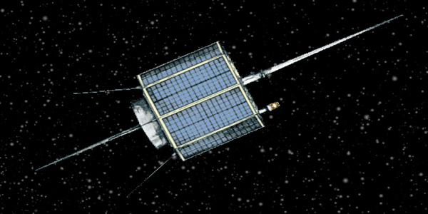
a typical depiction of amateur radio satellite – OSCAR AO-7
Theoretically, a satellite that has an orbital altitude between 200-2000 Km above the earth is termed an LEO satellite. However, most of the amateur communication satellites of this class have orbital altitudes between 350-1600 Km. The ones that have lower altitudes within this range are usually smaller, lightweight birds (satellites) and are mostly of the Nanosat or CubeSat class. Being closer to the earth, they have a shorter distance between the earth station and hence have lower Free Space Loss (FSL) thus being able to work with lower TX power and modest antennas. Typically, they carry cross-band FM repeaters for communication.
On the other hand, the satellites placed at higher altitudes within the defined segment of LEO are usually more complex, and heavier MicroSats. Most often they tend to carry a linear transponder that allows the mode of communication like CW, SSB, PSK31, etc. Being at higher orbital altitudes, their path loss (FSL) between the ground station is higher thus requiring perhaps a bit more TX power but more importantly better antennas for communication.
Most of these satellites have a continuously transmitting beacon in addition to the 2-way communication transponder or repeater. As we noted in our article on Space Radio Propagation, all these LEO satellite communications links suffer from various natural effects including primarily those of Doppler shift and Faraday rotation. Our amateur radio ground stations need to account for these factors to be able to establish reliable contacts.
Some of the important factors that we must consider at this stage are…
- Operating modes based on modulation.
- Operating modes based on frequency bands.
- Polarization of antennas for communication.
- Effects of Doppler shift and mitigation methods.
- TX power and antenna gains typically needed.
- Tracking and locating satellite passes.
Let us examine the above factors in further detail to get a better insight.
Modulation modes of amateur radio LEO satellites
Apart from a CW beacon featured by all amateur satellites, the primary factor that sets them apart from one another is the modulation modes supported by them. Most of them support either analog modulations or digital modulations or both for establishing two communication. The equipment carried onboard the satellites are generally either of the following two.
- Linear Transponder.
- FM cross-band repeater.
Linear Transponder
The satellites that carry linear transponders are the ones that receive the incoming signal across a narrow designated band of frequencies. Thereafter, they translate the incoming signal to another band of frequencies using a mixer and local oscillator. The output frequencies after linear translation are invariably on an entirely different band than that of the incoming signal. For instance, a 2m band incoming signal might be translated to the 70cm band or vice-a-versa.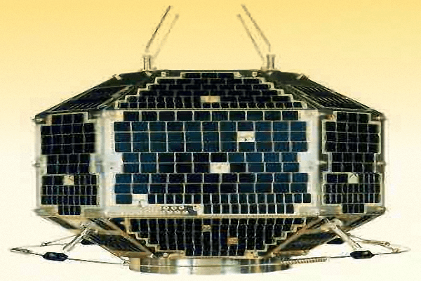
Fuji FO-29 (JAS-2) is a typical linear transponder type satellite for amateur radio service
On the other hand, a non-inverting mixer arrangement will retain the sideband mode to that of the original uplink transmission. The uplink USB transmission will remain USB while the LSB will remain LSB. It will also cause tuning or Doppler-related shifts to follow the same direction of frequency change. An increase in tuned frequency across the uplink band will increase frequency on the downlink band and vice-a-versa.
Therefore, the entire process of maintaining proper tuning and maintaining continuous signal acquisition during satellite communications while in an LEO satellite pass is perhaps a bit more complex and requires proper operator skills and tools at the ground station. Moreover, one must not forget that while working a mode like SSB, any drift of the relative carrier frequency while in QSO, unless continually and dynamically compensated, could lead to utter disaster. A few tens of a few hundred hertz of ongoing frequency tuning drift away from the virtual frequency position in a suppressed carrier SSB may make it quite hard to comprehend what is being spoken.
The saving grace is that the rate of frequency shift caused on account of dynamic effects like Doppler is usually slow and skilled amateur radio satellite communications operators can easily handle it either manually or with assistance from either automatic or semi-automatic station-based tolls and equipment. However, the bottom line is that to be able to compensate for such effects, it is important that the operator is aware and well versed with these phenomena.
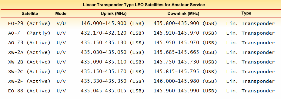
Table of basic operational specifications of some of the popular amateur satellites with linear transponders that are currently active at the time of writing
FM Cross-band Repeater
The FM repeater-based LEO satellites take away most of the difficulties cited above in relation to the linear transponder variety of satellites. That is the reason why we find that the FM repeater-type satellites have become very popular over the years for amateur radio satellite use. Not much skill is required to make amateur satellite-based contacts using these satellites. Even a novice can get a hang of it in very little time and start making contacts. We often call these satellites as EasySat.The reasons for the ease of using FM repeater satellites are manyfold…
- They work on fixed single uplink and downlink frequenies.
- Any drift in Uplink frequency is not reflected on the downlink.
- FM by nature is immune to small offsets in tuning frequency.
- These satellites orbit at lower altitudes with lower path losses.
- Shorter path distance means less TX power and smaller antenna.
Let us now expand on the above points to understand what they eventually mean to our satellite-based QSO.

A typical CubeSat with a small form-factor used to carry FM cross-band repeater for amateur use
Since there is no frequency translation involved here, the signal received at the satellite is demodulated to its baseband audio. Any shift in the incoming carrier frequency due to the uplink Doppler effect does not get reflected to the downlink. The extracted baseband audio is thereafter modulated once again onto the correct downlink frequency. Hence the downlink signal emission from the satellite is spot on the designated frequency after having discarded any shift caused by the uplink.
Of course, the downlink path will encounter a fresh bout of Doppler shift but the effects of uplink and downlink shifts are not cumulative.
This brings us to the most important factor that makes the FM repeater-type satellite tick… It is the FM modulation itself… Unlike a mode like SSB that traditionally requires the missing carrier to be regenerated by the demodulating receiver to work, the FM signal carries its own integral carrier with it in its modulated signal. Therefore unlike SSB which makes it difficult to generate a carrier at the receiver for a drifting signal, the FM has no such issues. As long as the entire signal falls within the receiver’s and its demodulator’s passband there is a very little problem. The FM demodulator can easily reproduce the baseband audio by using its own self-contained carrier reference.
In a nutshell, it is relatively a cakewalk working with FM cross-band repeater-type satellites. Of course, the Doppler shift is omnipresent while dealing with LEO satellites but it is far less a problem with FM. A clean detection and demodulation of FM are possible both at the ground station as well as the satellite end as long as the signal falls within the receiver channel bandwidth. Small Doppler shifts do not matter. Moreover, FM has a unique ability to lock on to the signal once acquired, and thereafter track its carrier in the demodulator (within certain limits) using various means like the Phase-Locked Loop (PLL), etc.
The Doppler shift on 2m for amateur radio satellites usually is well within ±3 kHz maximum. However, for a 70 cm band link, a slight adjustment may be required in the case of some satellite passes where the maximum Doppler shift may be around ±9-10 kHz… Usually, it is much less. The extreme shifts happen only when the satellite is close to the horizon at low elevation angles and it gradually decreases as the satellite rises higher into the sky.

Table of basic operational specifications of some of the popular amateur satellites with FM repeaters that are currently active at the time of writing
Typical Mode Designations based on Frequency Bands
Amateur radio satellites have traditionally been designated on the basis of their uplink and downlink frequency band combinations. The original system was to use a single alphabet designator which has now been replaced by a two alphabet combo in X/Y format. We still find both formats being used in various literature references related to satellite communications.
The most frequent old format designators
- Mode-A: 2m (145 MHz) Uplink / 10m (29 MHz) Downlink
- Mode-B: 70cm (435 MHz) Uplink / 2m (145 MHz) downlink
- Mode-J: 2m (145 MHz) Uplink / 70cm (435 MHz) Downlink
The new format designators
- Mode-V/U: 2m (145 MHz) Uplink / 70cm (435 MHz) Downlink
- Mode-U/V: 70cm (435 MHz) Uplink / 2m (145 MHz) downlink
- Mode-U/S: 70cm (435 MHz) Uplink / 13cm (2400 MHz) Downlink
- Mode-L/U: 23cm (1268 MHz) Uplink / 70cm (435 MHz) Downlink
- Mode-L/S: 23cm (1268 MHz) Uplink / 13cm (2400 MHz) Downlink
- Mode-L/X: 23cm (1268 MHz) Uplink / 3cm (10450 MHz) Downlink
- Mode-V/S: 2m (145 MHz) Uplink / 13cm (2400 MHz) Downlink
- Mode-S/X: 13cm (2400 MHz) Uplink / 3cm (10450 MHz) Downlink
Out of all the above, it is quite common to find that most LEO amateur satellite communications are conducted using V/U or U/V mode transponders or repeaters. This combination of frequency bands is very convenient as it allows amateur operators to use some of their existing radio equipment without having to make any further substantial investment. Other combinations that involve a 23cm (1268 MHz) band are also occasionally used by a few known satellites. The geostationary satellite QO-100, however, uses the S/X mode since it carries S/X band linear transponders.
Antenna polarization for satellite communications
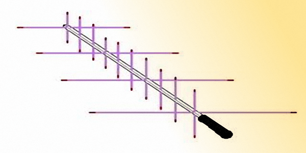
A typical light-weight hand-held dual-band Yagi antenna with linear polarization used by many amateur radio operators
In a satellite communications environment, there are several factors that make polarization matching complicated. In the case of amateur LEO satellites, it is a total nightmare. There are two effects that tilt the applecart. The first of the two is the Faraday effect (see Space Radio Propagation for more info) which results in rotation of the polarization of the radio signal passing through the ionosphere that lies in the path between the satellite and the earth station. The choice of lower frequencies like VHF/UHF makes matters worse. The lower the frequency, the greater is the magnitude of unpredictable Faraday rotation.
The second reason is that most of the amateur radio satellites barring a very few are all low-cost birds that do not have any kind of attitude stabilization. In other words, they freely roll, pitch, yaw, and tumble around as they orbit the earth. Hence all antennas onboard the satellites continuously and randomly alter their orientation and consequently their polarization. Please remember that in this article, we are primarily focusing on typical amateur radio LEO satellites and not referring to satellite communication using commercial or military satellites that mostly employ elaborate 3-axis attitude stabilization to ensure that the orientation of those satellites are always consistently pointing towards its sub-satellite point on earth.
Despite the effects of Faraday rotation and the orbital tumbling of the satellite resulting in a continuous and random change in signal polarization, the radio amateurs manage to establish contacts and conduct QSO via satellites. One might ask, how do they do it?
Negotiating Linear Polarization Mismatch
The first reason is that unlike commercial applications radio amateurs do not seek guaranteed reliability and continuous availability of the communication link. If the link is available for enough time that is suitable for conducting a QSO, then it fits the bill.Secondly and more importantly, the polarization mismatch scenario is after all not as gloomy as it may appear to be at first sight. We often assume that unless the signal polarization reaching the antenna is truly matched, there would catastrophic communication failure. Such an assumption is quite untrue. We have all been told that if the vertical to horizontal (90°) polarization mismatch occurs, the theoretical loss will be infinite while the practical attenuation will still be quite unacceptable to the tune of 20-30 dB. I agree with what is said… But how many of us have tried to find out as to what would be the attenuation if instead of 90° mismatch, it was to be either 45°, or 60°, or 75°, and so on? What is the maximum mismatch angle that we could tolerate and practically get away with?
Loss(dB) = 10 x Log(Cos2θ)
Where θ is the mismatch angle.
Based on the above, here are a few loss numbers to consider for various mismatch angles.
- 30° – -1.25 dB
- 45° – -3.00 dB
- 60° – -6.00 dB
- 75° – -11.7 dB
- 80° – -15.2 dB
- 85° – -21.2 dB
Based on our observations above, it is evident that for amateur radio satellite communications, a certain amount of polarization mismatch is not so much of a deal-breaker. For instance, if we have a reasonably good SNR during satellite access, perhaps we have enough margin to accommodate 6-12 dB additional loss and yet maintain good communication.
In other words, the antenna polarization mismatch at any instant in time could rise to as high as 60-75° without a disruption in QSO. If we have a great high gain antenna array for satellite communications then we may probably have enough SNR margin to accommodate as high as 80° polarization mismatch without any issues. Remember that most amateur radio satellites are fairly low altitude LEO birds with pretty low path link loss in comparison to other ones like the geostationary satellites.
Circular Polaraization to address Mismatch

An animation of the way circular polarized radiation produced by an antenna travels through space.
Firstly, let us understand that the circularly polarized antenna radiations may be of either of the two types. The Right-Hand Circular Polarization (RHCP) or Left-Hand Circular Polarization (LHCP). The point to remember is that the direction (Sense) of polarization rotation of antennas at both sides of a link must be identical. In other words, both the TX and the RX stations must either employ RHCP or LHCP. In case, one end of the link uses LHCP while the other uses RHCP or vice-a-versa, then the loss could be unacceptably large thus rendering communication almost impractical.
Here are a few important takeaways of the use of circularly polarized antennas…
- If both ends of the link use RHCP or LHCP polarization then the mismatch loss is practically zero.
- If one end is RHCP while the other is LHCP or vice-a-versa then it causes very high attenuation loss.
- If one end uses linear while the other end uses circular polarization (irrespective of RHCP or LHCP) then the loss is consistant at -3 dB only.
The earlier amateur radio satellites all used linear polarized onboard antennas for both the uplink as well as the downlink. Due to the constant tumbling of satellites in orbit and Faraday rotation, their polarization as seen at the earth station used to constantly vary. Those amateur earth stations that used linear polarized antennas used to experience different degrees of continuously varying polarization mismatch and consequent QSB as we explained earlier. Those earth stations that used circularly polarised antennas received QSB free signals with a small fixed additional loss of only -3 dB. It was a happy situation since there were no inconsistencies.
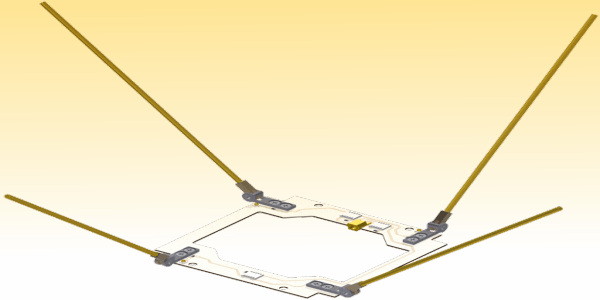
A typical configuration of a Canted Turnstile anteena mounted on most LEO amateur satellites for the 70cm band.
This brings us to a small problem that one might expect. Since most of the onboard circular polarized antennas are RHCP, one might expect the corresponding antenna at the amateur earth station to also be RHCP. However, a few satellites may be designed to use LHCP.
With a mixed variety of available satellites where some use RHCP and the others use LHCP, do we have a practical problem? what would we, the amateur operator do? Do we install two sets of link antennas, one with RHCP, and the other with LHCP? Or, do we set up complex polarization switching arrangements using antennas like the Crossed-Yagi?
Don’t fret… The practical situation for us is not as bad as it might appear to be. Now, I am going to bust a few popular myths that have percolated down from what we learn about the textbook scenarios related to professional commercial satellites. All commercial communication satellites are fully attitude stabilized in all 3-axis. Their orientation vis-a-vis any point on earth is geometrically fixed. Their circular polarised antennas have considerable gain and have good directivity with radiation patterns concentrated towards their coverage footprint on the earth. Hence a corresponding earth station antenna with proper polarization orientation is needed to optimize communication. In such cases, polarization orientation mismatch is not acceptable.
In the case of amateur LEO satellites, most of them are freely tumbling unstabilized objects with only a few that feature some kind of basic stabilization. The nature of attitude stabilization is usually a single-axis spin stabilization. By and large, due to the lack of orbital attitude stabilization, one never knows where the antennas are pointing as the satellite continues to tumble. It may well be pointing away into outer space at some point in time due to the tumbling movement. How do we maintain contact with the satellite? The answer is simple… We can not have high gain, direction pattern antennas onboard these satellites. These antennas need to be nearly omnidirectional in 3D space. That is precisely what is done…
RHCP or LHCP – what to use for working LEO amateur satellites?
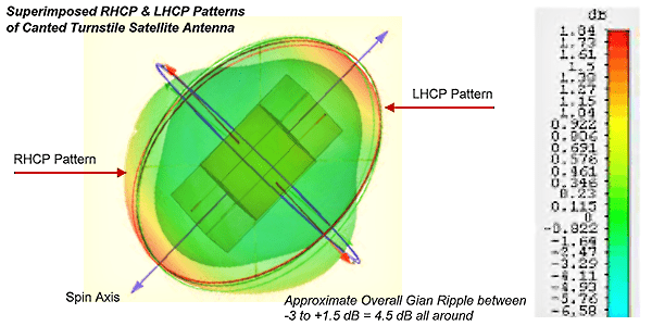
Canted Turnstile antenna onboard an amateur LEO satellite producing both RHCP and LHCP with acceptable variation in radiation strength levels all around in 3D space as the satellite tumbles around in orbit.
Therefore amateur radio LEO satellites, even when they use circular polarization on a particular link, always produce a signal that has mixed RHCP and LHCP in any direction at any time during its tumbling flight in orbit. As the satellite tumble, the signal strength modulation on account of polarization between RHCP and LHCP is fairly low. If we account for a few extra dB of margin in our link budget, it does not really matter whether the earth station antenna is RHCP or LHCP. For those who still believe that amateur circular polarized antennas must be RHCP to match the published specifications of the satellite antenna, think again… If one thinks it is always RHCP, then what happens when the satellite tumbles to face outer space? We still do make contacts, don’t we? But in this condition, the back of the satellite antenna is facing the earth. Hence, the polarization at the back is no more RHCP. It is LHCP. That’s basic science. So, how do we still manage to continue working via that satellite? Isn’t it obvious? The satellite antenna produces mixed polarized signals in all directions, with enough RHCP signal towards earth even when the signal toward earth should have been LHCP based on its attitude orientation.
The bottom line is that we need not worry about our circular polarized antennas being RHCP or LHCP. For most amateur radio LEO satellite communications purposes, it is immaterial. One could use either polarization under normal circumstances unless someone is trying to conduct some special experiment.
How to mitigate detrimental effects of Doppler Shift
We have discussed the phenomenon of Doppler shift as applicable to amateur radio satellite communications in our article Space Radio Propagation. You could check it out. Earth-orbiting satellites always produce a Doppler shift in the received frequency that appears to be either higher or lower than the actual transmit frequency from either end of the satellite link. This is caused due to the relative velocity between the satellite and the earth station. All satellites except geostationary satellites due to a zero effective relative motion between the satellite and earth station cause this phenomenon.
Since the magnitude of the Doppler shift is proportionate to the frequency, the frequency shift experienced on the 2m band is almost one-third of what it is for the 70cm band. Typically an LEO amateur satellite pass produces approximately a maximum of ±3 kHz shift on 2m and ±9-10 kHz on 70cm band. These extreme shifts happen when the satellite is near the horizon at low elevation angles and gradually becomes less as the satellite rises higher in the sky.
For typical V/U or U/V mode FM repeater communication using EasySats, this is hardly a problem, especially on the 2m link. Once tuned, the FM receiver on either side of the link can comfortably remain locked on to the frequency due to the inherent characteristics of an FM receiver. On the 70cm link too, there is not much of an issue though a slight retuning of the transceiver frequency might be required once or twice during the entire satellite pass. The FM receiver demodulators handle the rest.
Those working linear transponder satellites need to, however, make an almost continuous correction to counter the effects of the Doppler shift. An SSB or CW operator can continually manually tune the transceiver gradually or use the RIT to maintain the received signal integrity and quality. This method works well since the rate of doppler shit is slow and in a know direction. However, modern software utilities are available that allow the transceiver to be tuned automatically and continuously during a satellite pass and apply frequency correction in real-time. A CAT control arrangement between the PC running the software and the transceiver does the job neatly.
Antenna gain and TX power needed for working LEO satellites
The short answer is, Not Much… Working with most of the popular amateur LEO satellites is fairly easy. Many of the lower altitudes FM LEO sats like the AO-91, AO-92, etc are accessed by many operators around the world with a simple 2m/70cm hand-held transceiver (HT) with 5-10W TX output and a simple a 1/4λ vertical plugged into the rubber duck antenna socket. Some operators have also reported using the standard antenna that comes with the HT. Although these minimal equipment contacts may not be very robust or reliable, they are possible.
A typical average amateur satellite operator may choose to work with his HT and a hand-held dual-band (2m/70cm) light-weight Yagi. It may be a small Yagi with 3-elements for 2m and 5-elements for 70cm, all assembled on a 1-1.5m long hand-held plastic boom with a handle at one end. Many amateur radio operators enjoy satellite communications with this simple setup.
A proper base-station FM dual-band 2m/70cm transceiver running 25-50W is also quite common. Such installations may use either fixed, omnidirectional antenna like the Quadrifilar Helix (QFA or QHA), the Eggbeater antenna, Turnstile, etc or choose to go for dual-axis Azimuth/Elevation (Az/El) rotator mounts with larger Yagi, Crossed-Yagi, Axial-mode Helix, etc. The higher the antenna gain availability from horizon to horizon on all sides, the better is the SNR margin and consequently resulting in more robust and reliable communication.
The higher orbiting LEO satellites like many of the transponder type payload-carrying birds usually require a better-equipped station out of the type of configurations described in the above paragraph than that needed for working the EasySats.
DXing with LEO Satellites
One might ask, what on earth is satellite DXing? Don’t these satellites have well-defined coverage area footprints? So, everyone gets to communicate across the same range, Isn’t it? Well, the answer is NO, they don’t… Many of the regular amateur LEO satellite users do not get to exploit the satellite coverage to its fullest. Moreover, most of them are blissfully unaware of their limitations.

A typical 70cm circular polarized earth station satellite antenna mounted on an Az/El rotator also along with a 2m version of the crossed-Yagi (not shown in this picture).
A typical amateur LEO satellite would perhaps be transmitting no more than 1-2W on its downlink. We need to be able to hear the satellite transmission first before we could hope to work it.
The satellite signals received at the earth station are weakest when the satellite is at a low elevation near the horizon. This is the position that yields the maximum possible range coverage. However, with the usual types of antennas used by most amateur satellite operators, one does not hear the satellite until it rises fairly high. With simple antennas that are used by most people, the communication quality acquisition will only occur when the satellite would be at elevations greater than 30° or more. As a result of this, the effective radius of communication becomes smaller. Typically, one might expect this coverage radius to be no more than 70% of the footprint radius, or perhaps even less.
Therefore LEO satellite DXing that could ensure at least 90% footprint radius coverage would require an earth station antenna that is mounted in the clear with unobstructed Fresnel zone clearance to the horizon. It has to have a high gain with narrow beamwidth. Invariably, this condition would not be fulfilled by simple omnidirectional antennas or hand-held Yagis. One would require a proper Az/El rotator-mounted antenna system. Please do not forget that the noise level at a low elevation angle is also more due to earth reflections and man-made noise. This further compromises the SNR at low elevation angle thus requiring higher gain and low beamwidth antenna to overcome the additional noise-related challenge.
LEO satellite DXing requires a good antenna system with a dual-axis Az/El rotator set up at a decent height above ground with visual clearance to the horizon in all directions. Those with more modest and relatively compromised antennas rarely manage to cover more than half the range than what the satellite has to offer. It is never the power of your transmitter that really matters. It is the antenna that makes or breaks a satellite DX QSO. Try to invest in a good Crossed-Yagi or axial-mode Helical antenna system with an Az/El rotator to open up new vistas in amateur LEO satellite communications.
All said and done, working with amateur radio satellites is relatively simple, does not require too much equipment, does not need large real-estate for antennas, yet it provides good fun. I haven’t gone into communication aspects related to our one and only (at the time of writing) geostationary satellite. This is QO-100 (Es’hail-2) that simultaneously covers Africa, Europe, most parts of Asia, and parts of Brazil. I will dedicate a separate detailed article for QO-100 satellite operation, link budgets, and the kind of equipment and antennas needed to do so.

Contents
- 1 Amateur Satellite Communications – An Introduction
- 2 Linear Transponder
- 3 FM Cross-band Repeater
- 4 The most frequent old format designators
- 5 The new format designators
- 6 Negotiating Linear Polarization Mismatch
- 7 Circular Polaraization to address Mismatch
- 8 RHCP or LHCP – what to use for working LEO amateur satellites?

(27 votes, Rating: 5.00) - Please vote the article with your valuable star rating. Thanks! Basu (VU2NSB)


SSN SSNf(10.7) – Real-time Solar Data