Amateur Radio Station (Ham Shack)
A typical amateur radio station comprises two sets of hardware. They are a set of outdoor hardware comprising of the antenna and related stuff and a set of indoor hardware that comprises the transceivers and associated peripherals. The outdoor and the indoor hardware are interconnected through a transmission line that forms a very vital part of the overall radio station setup, however, unfortunately, it is often taken for granted and treated as trivial.
Typically, all the indoor hardware is kept in a separate room dedicated to amateur radio operations. It is called the Ham Shack. At times, due to various limitations, one might not be able to allocate a separate room for the Ham Shack but they often choose a quiet place in the house to set up all the radio gear.
Let us start by examining the basic requirements of a ham shack. Thereafter, we will try to look into the plethora of equipment that goes into a typical ham shack. We will conclude this article by finally examining the most vital components of the radio station, namely, the antenna and transmission line.
What are the basic requirements for a good Ham Shack?
For setting up a Ham shack, one would need a small or a medium-sized room that is preferably located in a quiet corner of the house with minimal disturbance and noise. Some amount of furniture including tables, racks, and of course a comfortable chair are some of the basic requirements.

A typical layout of a Ham Shack with a variety of radio communication equipment, peripherals, test-instruments and station computers.
A reasonable amount of furnishing including curtains, floor carpet, and regular upholstery are recommended because of their sound-absorbing characteristics. This way one can avoid undesired room echoes and reverberations. This plays as a factor for those who might use desktop microphones, however, those using a headset with an integral boom microphone are usually immune to these adverse effects.
The type of lighting and other general items like fans, etc in the Ham shack must be carefully chosen. Avoid modern fancy electric lighting systems. They are invariably noisy.
Let us list these as well as other factors below for ready reference…
- Ham Shack should be located at a quiet place in the house away from the hustle and bustle of household activity.
- Try to locate the Ham Shack as far away from the kitchen or parts of the house that contain a TV, home theatre, or other prominent electrical equipment.
- A Ham Shack with a door is advisable as it helps in cutting out noise from household conversations and other activities.
- Adequate fabric furnishing material in the Shack helps in reducing reverberations and makes you sound better when you transmit.
- Make provision for the entry point of transmission lines into the Ham Shack and pay attention to preventing moisture and water seepage during rains.
- Make provision for a good electrical ground point in the shack that is separate from the household electrical ground.
- Never use modern electric lights like LED or CFL lamps in the shack. Also, avoid tube lights that use electronic chokes. It is best to use incandescent bulbs or tube lights with inductive chokes.
- Avoid using non-essential SMPS power supplies like sundry gadget chargers, etc in the Ham Shack to minimize RF noise.
- Avoid electronic regulators for fans and modern air conditioners with inbuilt DC-DC converters, etc. All of them contribute to RF noise.
- Avoid using Power-line Carrier communication-based electrical appliances in the shack. PLCC signal on the power line is also a source of RF noise that can sneak into other RF-sensitive equipment.
- If your house uses PLCC network, then make sure that the power-line entering your Ham Shack passes through an adequate in-line filter to remove PLCC signals.
- Tables with shelves to neatly place radio station hardware make sense. A comfortable chair for the operator is also important.
Applying due diligence while planning the layout of the Ham Shack at the start will save a lot of trouble later. It would never be enough to emphasize that good care must be taken to ensure minimum possible extraneous electrical noise sources in the Ham Shack. In a desire to jazz up their shacks, many overzealous operators use fancy lighting schemes using modern types of lights and fixtures. This is perhaps the worst decision that one might take and regret later. One might eventually end up with a snazzy looking shack but an utterly noisy one too.
What are the operating Radio Gear and other hardware in a typical Ham Shack?
Here are some of the essential pieces of hardware and interface arrangements that one would need in a typical Ham Shack. Some of these are essential while the others might be optional, depending on the type of operation that one might like to conduct as an amateur radio operator.
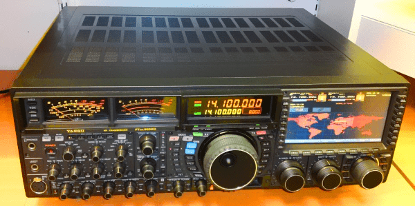
A radio transceiver for a serious amateur radio operator.
Morse (CW) Key: – If you operate CW, then the proper location on the table of the CW Key vis-a-vis your seating position will make operating CW a pleasant joyful exercise. The CW key should be mounted on a reasonably heavy and sturdy base to ensure that it would not move, slide, or topple while you happily key away. Felt pads or rubber feet below the baseplate of the CW key will add to mechanical stability and also prevent scratches on the desktop.
Computer (PC): – Most modern amateur radio stations might also have SSTV and digital radio communication capabilities using various modes like RTTY, PSK31, FT8, etc. Therefore, a PC in the Ham Shack, either a desktop or a laptop, is inevitable to run various software to encode and decode these modes. Place the PC at a reasonable distance away from the RF gear and also use a separate power socket for the PC power input.
Audio Interface Cable:- If you are a Digi-mode operator, you would need to interface the PC to the transceiver to carry the AF modulated sub-carrier of the digital mode signals between the PC and the TXR. A typical audio interface cable would have proper types of connectors that are compatible with the model of the transceiver that one uses. Moreover, it is recommended that one should choose an interface cable that provides electrical isolation on both the AF lines. The use of isolation transformers is recommended. Similarly, the other control lines like the PTT or Keyer lines must also be isolated preferably through optoisolators.
CAT Interface Cable: – Most modern transceivers provide the feature of controlling it from a remote GUI control software that runs on a PC. A variety of software is available that supports various different interface protocols used with different rigs. CAT stands for Computer-Aided Transceiver. Some operators prefer o to use CAT not only to control and operate the transceiver but also to manage and control other peripherals like the antenna rotator, etc. This requires a dedicated CAT control cable to interface the PC that runs the software and the transceiver.
Transceiver Power Supply:- The modern amateur radio transceiver usually requires an external power supply unit that provides DC power at 12V (13.8V). In the good old days, most of these power supplies were linear regulated types with a regular 50/60 Hz step-down transformer and rectifiers. Typically, these power supplies are clean from the RF noise perspective. Even today, I would recommend a sturdy linear regulated power supply for the transceiver.
Nowadays, a switched Mode Power Supply (SMPS) is another option. An SMPS is very lightweight, small in size, and relatively inexpensive. A well-built SMPS with adequate EMI/RFI filters and designed specifically for radio communication equipment generally works satisfactorily. However, a large number of radio amateurs often make the blunder of using general type SMPS that is essentially meant for other purposes. They end up with a station set up where the noise floor, especially on the HF bands, goes up significantly (perhaps by several S-units). The overall receiver performance degrades due to the additional RF noise from the SMPS. This situation may be managed to an extent by the use of a variety of additional external filters and RF chokes on cables. Yet the end result is never as good as what may be obtained from a linear regulated power supply.
A word of caution for anyone who opts for an SMPS power supply for an HF rig. Do due diligence while choosing an SMPS. Never fall into the temptation of picking up a unit that is not built for use with HF radio transceivers. If one were to ignore this, then the receiver’s performance might be severely compromised. One might not be able to copy and work many DX stations on account of the additional RF noise. For typical VHF/UHF use, an SMPS does not pose many problems.
RF Linear Amplifier (PA)This is an optional and a non-essential item. Although an RF linear amplifier (PA) to enhance the power output of a radio station does indeed serve a purpose under some conditions, it is rather over-hyped amongst a large section of operators. I would rather trade a PA for even a moderately better antenna. The improvement in radio station performance on account of a better antenna is far more than that of an RF linear amplifier. The enhanced antenna lets me put out more effective radiated power (ERP) towards the DX station and also allows me to copy him stronger and better. On the other hand, an RF PA will only increase my radiated power but will do nothing to improve a copy on the DX station. Remember, unless you can hear him, you can’t work him. To see why the antenna is the the most vital part of an amateur radio station, you might like to read the post on To invest in better Radio Rig or better Antenna.
When might or might not an RF PA be justified? Here are a few typical situations…
- It helps when one might be trying to break into a pileup on a rare DX or a DXpedition. However, you must first be able to copy the DX well enough. The PA will only make your signal stronger at the DX end and hence help in catching the DX operator’s attention by making you stand out from the crowd.
- If your radio station is immaculately set up so as to have a lower than average receiver noise floor by addressing and containing all plausible sources of local QRM, and EMI/RFI, then only an RF PA would make sense. In such a case, since you might be able to generally copy weaker signals, a PA at your end might help establish a contact when the DX may be facing the ill effects of higher local noise levels.
- If the overall noise level (especially local QRM to extraneous man-made sources) at your station is high, then using an RF PA will serve no purpose because you won’t be able to copy the DX anyway. Hence, a QSO would probably be out of the question.
- Perhaps one should consider working to eliminate local QRM to the maximum possible extent and thereafter consider a better antenna rather than thoughtlessly opting for a PA in a wishful hope to mitigate the shortcoming of the amateur radio station installation.
Antenna Tuning Unit (ATU): – Although the term ATU is popular, it is rather a misnomer. It does not tune the antenna in any way. It is actually an impedance transformer for matching the impedance (complex impedance) presented by the antenna system at the Ham Shack end of the transmission line to the output impedance (resistive) of the transceiver. As was common in the good old days, it might make more sense to call it a Trans-match instead of ATU. Most HF amateur radio transceivers come with a built-in ATU that is capable of a certain amount of impedance mismatch at the antenna terminal of the transceiver.
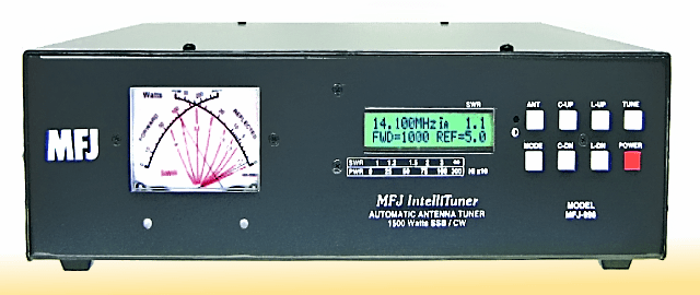
A modern-say ATU with automatic as well as semi-automatic tuning capability.
The older transceivers with vacuum tube final RF power amplifiers and most vacuum tube outboard PA are capable of inherently matching moderate antenna system impedance mismatch on account of a PI-network LPF section at their outputs. Although unlike the ATU of modern solid-state rigs, the tuning capability of the PI-networks is manual and not automatic, they tend to be very robust and often handle larger than 3:1 SWR.
Outboard ATU is available in the market to be connected in line with the transceiver output. These standalone ATU usually have the ability to handle larger impedance mismatches and may often cover SWR of 16:1 or even higher. These are used when the antenna system impedance mismatch as seen at the transmitter end is higher than the 3:1 SWR handling capability of the transceiver’s ATU. They may also be used with those transceivers that do not feature a builtin ATU. One classic example is the popular Icom IC-706 MK1G that is still used by many radio amateurs around the world. Solid-state PA also normally requires an outboard ATU. Solid-state PA stages are typically broadband and hence do not utilize in-built circuits like the PI- network.
All said and done, an outboard ATU might appear to be a great solution to managing high SWR and many operators believe that the SWR match obtained through them results in utopia, the fact is that it is not so. Using an ATU to handle impedance mismatch resulting in SWR up to 3:1 is normally acceptable, however, correcting higher SWR at the transmitter end with an outboard ATU is usually not an optimum solution. While using antennas especially those with coaxial cable transmission lines, using an ATU to correct high SWR results in a rather high radio station inefficiency. A better solution would be to aim for a reasonably good impedance matching at the antenna feed-point end of the transmission line through a proper antenna system design rather than to use a shack side outboard ATU… However, that’s a story for another day. Meanwhile, refer to my post on Will low SWR always ensure a good Antenna setup?
SWR meter and RF Power meter: – Standalone SWR and RF Power meters are fairly common items found in a typical Ham Shack. Generally, these are inline instruments that measure the prevailing SWR, forward Power, and Reflected Power on transmission lines that connect the transceiver system to the antenna. These instruments are not required for a day-to-day radio station operation. They come in handy while doing the initial tuning or making adjustments to the antenna after installation or modification. Moreover, for regular use, most modern transceivers, as well as the ATU, usually incorporate these metering functions to the extent that one might need for daily use.
Some radio station operators place an SWR/Power meter permanently inline with the transmission line. Although, it does no harm because its insertion loss is quite low and totally acceptable but it is absolutely unnecessary to do so.
EMI/RFI Filters and common-mode RF suppressors: – While setting up radio station equipment in a Ham shack, despite the care and due diligence, one might occasionally find the need to apply additional means to suppress RF noise and common-mode currents that might slip through and flow on some of the interconnecting cables and transmission line sections. One might need to use Clip-on ferrite RFI suppressors, ferrite beads, common-mode toroid chokes, etc to further reduce RF noise-related residues that might still remain despite best Ham Shack set up practices. Going into details is beyond the scope of this introductory article, however, I will dwell on these factors in-depth elsewhere on this website.
What are the auxiliary station hardware for a typical Ham Shack?
In the previous section, we took a brief look at some of the operating hardware used in a typical amateur radio station setup. Let us now focus on some other instruments and hardware that might enhance the capabilities of a radio amateur to build and maintain his station. Deploying an efficient amateur radio station and thereafter maintaining, modifying, or upgrading it might require some of this equipment.
Soldering Station and Small Tools: – Quite often a good soldering iron would suffice rather than opting for a fullfledged soldering station. Whatever one might opt for must be of a required wattage rating for the job at hand. While a soldering iron is rated at 10-15 Watts for soldering electronic components on a PCB, an iron rated at 35-100 Watts might be required for soldering on larger heat-dissipating surfaces like cable connectors, etc. A set of hand tools like, forceps, pliers, wire cutters, screwdrivers, etc including a hand-drill or a table-mounted drill machine are also essential. It would be good to invest in a miniature table-vice and C-clamps to hold objects while you work with them. A coaxial cable stripper and perhaps an RF coaxial cable crimping tool are also very useful if you need to make your own RF cables. Another item that might be handy is an illuminated magnifier while working on PCB with miniature components.
Multi-meter or Volt-Ohm meter (VOM): – This is one of the basic must-have electrical instruments in any Ham Shack. The modern digital multi-meters (VOM) are low-cost portable instruments. Other than measuring DC resistance, AC and DC current, and voltage, most of these instruments offer additional functions. Some of these multi-meters can measure frequency in the AF spectrum, measure capacitance, test and check NPN and PNP transistors, etc. As the name suggests, a multi-meter is a basic multi-function measuring instrument that one cannot live without.
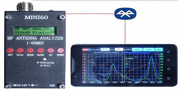
A typical modern-day antenna analyzer that is capable of working over a wide RF spectrum covering various amateur radio bands. They usually feature remote access and graphing capabilities involving several vital measurement parameters using BlueTooth connection to computers and mobile devices like the Tablet or even a mobile phone..
At this point, let us understand that an Antenna Analyser falls under the classification of instruments called Network Analysers. However, this instrument is a Scalar Network Analyser (SNA) as against another instrument of the family known as Vector Network Analyser (VNA). A VNA is a more complex instrument with additional measurement capabilities using a 2-port network model. Unless a radio amateur is into designing and fabricating antenna system RF parts that might require more advanced measurements, I would suggest that a regular radio amateur should stick to an SNA type regular Antenna analyzer.
RF Dummy Load: – A dummy load is a very basic passive RF unit with the sole purpose of terminating transmission lines with their characteristic impedance to simulate a near-perfect (1:1) SWR condition. The wattage rating or the power dissipating capacity of dummy loads vary. A low wattage RF dummy load can be used if conducting transmission line tests at the QRP level or while using it along with an instrument like the Antenna Analyser. However, while conducting a test with transmitters, the power rating of the dummy load must be proportionately higher.
Typically RF dummy loads have traditionally been a combination of several resistors with adequate aggregate power rating. They are either cooled by convection or forced air cooling, or by immersing them in an appropriate type of oil for better dissipation. These resistor type dummy loads must be made using non-inductive resistors because inductive resistors like the wire-wound type totally mess up with the effective impedance at RF. Nowadays, we also have Monolithic Power Resistors available that may be mounted on extruded heat-sink blocks to offer very low overall thermal resistance and hence dissipate fairly high power. The other benefit of monolithic RF resistors is that they offer excellent broadband frequency response characteristics, thus allowing these dummy loads to operate from DC (0 Hz) all the way up to 3-5 GHz with ease.
General purpose Oscilloscope:- A general-purpose Oscilloscope is a pretty useful instrument to have in a Ham Shack. For those of us who like to homebrew or experiment with electronic circuits, it is a must-have instrument. While dabbling into electronic circuits, an oscilloscope is like what eyes are to us in regular life. It allows us to observe electric voltages and signal waveforms at any point in an electronic system. A variety of oscilloscopes are available. Some of them are standalone units while others may interface with a PC that is used to display the results and control it. In the beginning, one might opt for an inexpensive unit that has a 25-35 MHz frequency response and features a dual-channel capability. This would suffice for most applications.
An oscilloscope also comes in very handy for monitoring one’s transmission by observing the modulation envelope. This would help in ensuring a clean modulation. In a typical HF radio environment, a simple wire loop placed near the output cable of the transceiver and connected to one of the vertical inputs of the oscilloscope would be sufficient to monitor the TX RF quality in real-time. There are many other applications limited only by the ingenuity of the user.
Spectrum Analyzer: – Although a Spectrum Analyser might not be an instrument of everybody, it serves as a very useful tool for those radio amateurs with more advanced capabilities. Unlike the Oscilloscope that displays signal entities in the time domain, a spectrum Analyser displays the same information in the frequency domain. It is akin to performing a Fourier transform on a regular waveform. A spectrum Analyser helps in observing, identifying, and measuring sidebands, splatter, spurious components produced by transmitters, etc in a radio station. It is also a vital instrument for measuring and displaying frequency response characteristics of amplifiers, filters, etc.
Spectrum Analysers usually have a builtin tracking RF signal generator that allows for various other 2-port RF measurements in conjunction with directional couplers and signal samplers thus making it a very versatile instrument with capabilities like that of VNA.
We dwell deep into various test and measurement procedures that are relevant to radio communication equipment under our website section on RF Tsting. Stay tuned and check out new articles that we continue to add on a regular basis.
Antenna and Transmission Line for a Radio Station
As I have said many times before, let me emphasize a basic fact once again… The optimization of the antenna System comprising of the antenna and the Transmission Line is most vital for the overall performance of any radio communication station. A radio station is as good or as bad as the Antenna that it has… Everything else is secondary. Those who believe in this adage are most likely to set up a far superior performing amateur radio station compared to the others who ignore this core principle. Shift your misplaced focus from the burning desire of acquiring a better and jazzier transceiver to acquiring a better antenna. It is guaranteed to pay rich dividends.
Having said that, let us take a quick look at some of the basic yet important dos and don’ts related to antenna systems.
One might ask, what is a better antenna? Does it mean that it must be a large high-gain antenna? NO, It doesn’t… Why do you keep emphasizing on the transmission line? What’s the big deal? I have the most expensive low-loss coaxial cable for my antenna. Isn’t that good enough? NO, unfortunately, it might not be enough, especially for HF radio antenna installations. What matters more is how you deploy the transmission line at your specific installation rather than how expensive or low-loss type it is.
On this website, I have several articles and posts that deal with various aspects of antenna and transmission lines. Therefore, over here, let us just summarize some of the important factors related to antenna system deployment.
- A better antenna is far more important than the latest transceiver with bells and whistles.
- A better antenna does not always mean a larger higher gain antenna.
- The published performance figures of an antenna need to be evaluated carefully because they are specified for optimum installation conditions. The actual deployment conditions at your QTH may never realize these performance potentials.
- The published gain of an antenna is true only for a specific elevation take-off angle and it does not mean that this gain will be available for all DX distances and propagation conditions.
- Typically, for better DX operation, the gain of the antenna that would be obtained at low take-off angles is what counts. This is usually far lower than the published gain of an antenna.
- Barring a few types of antennas like a vertical monoplane antenna with a radial ground plane system, most other antennas popular among radio amateurs depend on the installation height of the antenna above ground to determine their low take-off angle radiation capabilities.
- Remember, that on a DX circuit that usually requires low radiation take-off angles, at times even a simple wire dipole antenna at a good height above ground might outperform even a Yagi, Hexbeam, Moxon, etc that is deployed at a much lower height.
- Focus on how high you might be able to raise your antenna above ground. It is guaranteed to pay dividends. Usually, it is far easier and practical to raise a lightweight wire antenna like a dipole, etc quite high, while one might face logistic and operational limitations in raising to equal height a larger and heavier rotatable antenna.
- Pay extra attention to the transmission line between the antenna and the transceiver setup in the Ham Shack. Just having an expensive and low-loss transmission line is not enough. It is more important to properly deploy the transmission line.
- A transmission line as the name suggests must carry the radio signal between the antenna and the rig. It must not be leaky and radiate RF energy. The more leaky the transmission line, the more compromised will be the overall radio station performance.
- Ensure that the transmission line connection at the antenna feed-point is correctly interfaced to address impedance transformation, balance-to-unbalance factor, and choke/mitigate common-mode current being developed on the transmission line. All these must be achieved at the antenna feed-point end and not at the transceiver end.
- Do not shy away from using Balun, Unun, common-mode current chokes, etc as and when required at the antenna feed-point end to ensure that the transmission line is correctly interfaced with the antenna.
- Common-mode current (CMC) on a transmission line is the biggest culprit that is responsible for adding unwanted RF noise and rendering the radio station compromised and at times pretty useless. Never let the CMC unwittingly kill your radio station performance.
- Remember, that an ATU at the Ham Shack would certainly make the transceiver see a good SWR but it does not in any way improve the performance of a poor antenna system.
- Do not fall into the trap of being lured by dubious antennas that are available dime a dozen in the market. Anyone who offers a very small-sized (small form factor) antenna with magical performance is surely taking you for a ride. Just as there is no free lunch in the world, there is also nothing like a small magical antenna that could deliver great performance.
- Most of these magical antennas work by misconfiguring the transmission line at the feed-point, thus making the cable produce imbalance and a considerable amount of CMC. The cable acts as a leaky transmission line producing radiation. This results in an overall unsatisfactory antenna performance while producing unacceptable EMI/RFI and highly elevated noise floor at the receiver.
- Avoid indoor antennas, especially in a concrete building. The RCC construction of these buildings on account of the metal embedded floor, roof, beams, girders, and columns make the antenna quite inefficient with distorted radiation patterns. Moreover, they often produce high levels of RF field in the house or the Ham Shack that might not only be unhealthy for people but also for the sensitive radio equipment.
In this article, I have attempted to cover some of the vital factors that one must consider while building a Ham Shack and setting up an amateur radio station. Consider all these factors and pay attention to them.
List of Articles under this Section
Radio Communication Microphones Radio Communication Microphones - The Untold Story How to optimally set up and use a microphone in a radio communication environment? This is perhaps one of those questions that rarely tickle in the minds of radio amateurs. Their...Radio Transceiver S-Meter - Pitfalls to avoid Radio Transceiver S-Meter - Lesser known facts An S-meter of an HF radio transceiver is a very important instrument on the rig and is used extensively for signal reporting by amateur radio operators while in QSO. However, unfortunately,...


(17 votes, Rating: 5.00) - Please vote the article with your valuable star rating. Thanks! Basu (VU2NSB)


Ham Rig Reviews Coming Soon
SSN SSNf(10.7) – Real-time Solar Data