Fascinating Amateur Radio Communication
The website features a friendly navigation menu structure, a comprehensive in-site search engine, and tags clouds for articles and posts. A live chat facility is also available for interacting with VU2NSB. We recognize that many senior visitors with failing eyesight often find it difficult to read long articles due to the small font size. Every article page on this website has font size control buttons to enlarge the font to your liking. The website is fully responsive with fluid design thus rendering well on almost all devices including desktop computers, laptops, tablets, and mobile phones.
 Radio Equipment
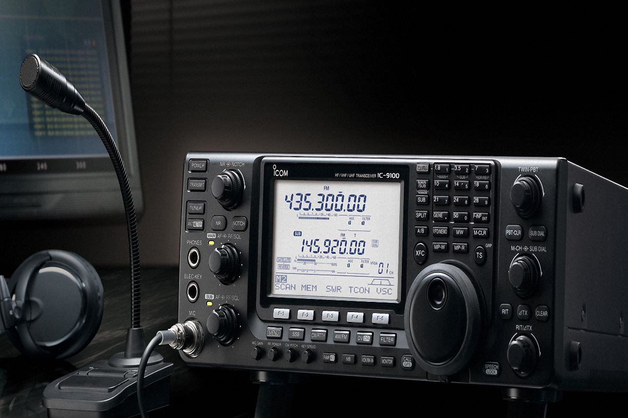
A typical amateur radio operator has a room full of wireless radio equipment. This is the Ham Shack. Mostly they are radio receivers, transmitters, or transceivers. Some of these could be of commercial origin while others could be self-made or home-brewed by amateur radio operators themselves. Other stuff may include antenna tuners, power supplies, SWR meter, etc.
As amateur radio operators, we all learn how to operate our station equipment effectively. However many of us seldom go beyond this stage. To get a better understanding we need to look under the bonnet. We need to figure out the limitations and strengths of our station equipment. We need to understand the various vital specification, parameters, and other important factors that are responsible for our transmitter, receiver, and other station equipment to perform as they do.
You will find a variety of articles and post about radio equipment on this site. Articles cover the theory, construction, and operation of amateur radio communication equipment. Apart from traditional radio equipment designs, modern concepts and technologies like Software Defined Radio (SDR), Digital Signal Processing (DSP) using either computer-based software or dedicated programmable hardware devices, Micro-controllers, Field Programmable Gate Arrays (FPGA), etc are covered in this website…. Read More.
 HamSphere 4.0
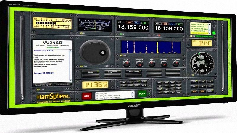
The wonder world of HamSphere 4.0 is a true gift of modern technology. It is the ultimate virtual amateur radio system. Unparalleled and unmatched in performance it has an uncanny resemblance to real HF SSB radio. HamSphere 4.0 offers VHF/UHF FM radio with simulated repeater networks, including vast paraphernalia of a realistic virtual HF amateur radio support system.
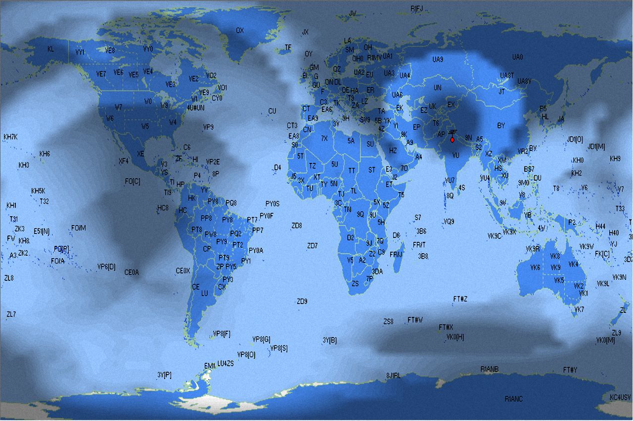
The strength of HamSphere is an accurate HF propagation model that tracks nature and replicates ionospheric behavior on a minute-to-minute basis. Solar activity and SSN determine propagation behavior. Exotic HF propagation modes like the Gray-line, Chordal hops, Trans-equatorial propagation, back-scatter, winter anomaly, etc are all simulated. HamSphere sounds and behaves like the real HF radio with both normal and split frequency operating capability.
HamSphere 4.0 offers a complete virtual amateur radio environment. It comes with a highly salable modular transceiver designed to match the best hardware transceiver. A plethora of realistic virtual antennas is available on HamSphere. This opens up a whole new world of ham radio for all. The experience is awesome which captivates the old-timer. It is also a boon for a new operator.
You don’t have to worry about going wrong and burning up your linear PA or melting antenna traps. Those with limited space in urban localities can now experience all the goodies of HF radio without having to put up big physical antennas. For the senior operators, no climbing of towers to make that little adjustment. The niche technology of HamSphere brings everything to your laptop…. literally as well as figuratively… Read More.
 Signal Propagation
Radio signal propagation from one location to another is vital for radio communication to exist. Various propagation modes come into play depending on the frequency band in use. At VHF/UHF and higher frequencies, the atmosphere of the earth has a significant effect on terrestrial propagation. However, for satellite and space communication several other factors like Doppler shift, Faraday rotation, etc also play a role. HF radio propagation is quite a different ball game. It is very interesting and intriguing the way the Ionosphere plays a major role in long-distance communication.
Ionospheric layers are dynamic in nature. They constantly change based on diurnal, seasonal, and many other factors. The declination of the earth and the activity of the sun play a very vital role. Proton flux, X-ray, and several other EM and particle emissions from the sun determine our ability to maintain HF radio communication on earth. At even lower frequency bands like MF and LF where the ionosphere has far less influence, we encounter the phenomena of surface wave propagation in its full strength and glory.
In the propagation section of our website we dwell deep into these topics with articles and posts. We try to follow the mysterious and fascinating science of radio propagation from the perspective of an amateur radio communication. With clear and concise articles we endeavor to make this intricate subject relatively easy to understand…. Read More.
 Antennas
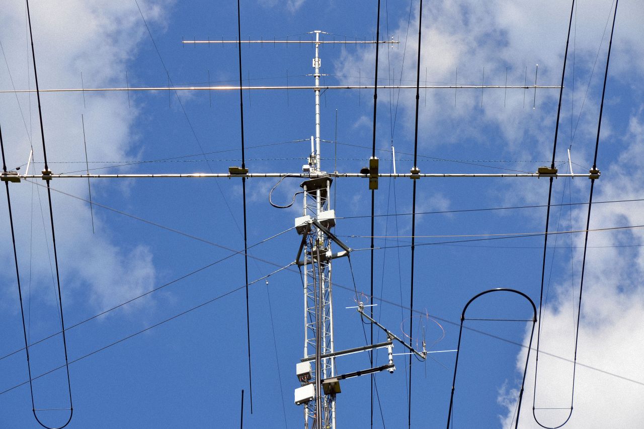
The antenna is the most vital part of any radio communication station. The antenna determines the efficacy of the radio station and consequently its ability to establish long-distance contacts through a hostile propagation environment. All amateur radio old-timers know this very well. A radio station is as good or bad as its antenna. Contrary to popular belief, it is not the transmitter power output but a good and effective antenna that enables good two-way contact. An average amateur radio operator does not work with very high TX power, yet communicates successfully around the world.
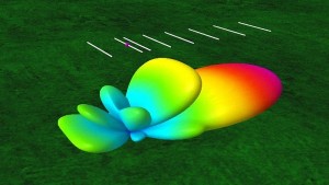
The need for a good antenna can never be over-emphasized. Unlike a power amplifier that gives us the advantage in only one direction of a two-way QSO, a better antenna leverages the advantage during both TX and RX. During TX a good antenna emulates a linear amplifier. Due to its gain, it produces higher Effective Isotropic Radiated Power (EIRP). This is akin to using a PA. During RX, the gain of the antenna manifests itself as a bigger aperture thus giving it the ability to effectively pick up weaker signals. There is no point in putting out more TX power alone. Unless we hear the far-end station we cannot work him.
I have always invested time, effort and money in ensuring that I have the best possible and well-tuned antenna. In the antenna section of this website, we discuss them threadbare. Various parameters of antennas, how to choose, what factors are important while deciding and how to set up amateur radio antennas are all discussed… Read More.
 RF Measurements
In the present day and age, amateur radio operators have many choices. All types of ham radio equipment including transceivers, peripheral station equipment, antennas, etc are all available at a price from commercial manufacturers. These types of equipment are adjusted and tuned at the factory. They follow the plug-n-play paradigm. It is thus a fairly trivial task to set up a functional amateur radio station.
It is an age of instant coffee and 2-minutes-noodles. A majority of amateur radio operators use commercially fabricated rigs and enjoy the hobby. Although there is nothing wrong with this approach, unfortunately, this leaves little room for tinkering and experimentation. Yet there are many who still like to do things their own way by exploring, experimenting, and designing/fabricating their rigs.
For those who wish to transcend the boundaries of radio as only an art, broaden their perspective, and dwell deeper into the science and technology of radio communication, a tacit understanding of RF measurement and general test and measurement techniques (T&M)would play a vital role.
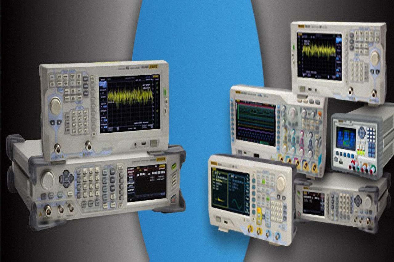
We have devoted a full section of this website to measurement techniques. Over a period we intend to progressively explore various nuances of RF measurement with reference to transmitters, receivers, transmission lines, antennas, and much more. We will cover all aspects of HF, VHF/UHF, analog, and digital measurements. Various technical parameters, their relevance, test setups, required equipment and measuring procedures that are vital to amateur radio communication will be highlighted and discussed… Read More.
 CW & Digi-Modes
Although analog radio-telephony is the most popular mode of communication on amateur radio bands, various digital data modes are also quite extensively used. These modes have their own pros and cons. Any mode of communication that uses binary symbols at base-band levels or those modes that require machines to encode or decode information are clubbed here under this category.
CW or Morse code is perhaps the world’s oldest method of radio communication. It is indeed a digital mode because signals have binary states. However, it is unique due to the fact that it does not need machines to encode or decode. It is human-friendly and rather than being a code, it is actually more like a language of pleasant-sounding musical notes. CW is very robust and can be used with simple equipment and has the ability to perform under the most hostile communication environment where all other methods fail.
Amongst classical amateur radio Digi-modes, RTTY is the oldest. PSK31, MFSK, QPSK, MT63, Olivia, Hellschreiber (Feld Hell), Throb, Thor, Contestia with many sub-flavors are some of the popular digital text or file transfer modes. A relatively new kid on the block is ROS, a wonderful weak signal robust digital protocol system. It provides DSSS, as well as FHSS, spread spectrum modes.
Nowadays, another mode called FT-8 which is an offshoot of JT-65 has taken the amateur world by storm. Although they are technological marvels allowing very weak signal communication, they are rather drab since they use a restricted format and do not allow free-form text. Although analog SSTV is essentially an analog mode using FM base-band sub-carrier modulation, we place it under this category since it requires machine encoding and decoding…. Read More.
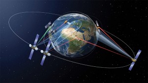 Space Radio
The first human effort to venture into the realm of space communication started with the launch of the Russian (erstwhile Soviet Union) Sputnik space orbiter in October 1957. Sputnik was placed in an elliptical orbit and sent out regular message transmissions. The signals were strong enough to be picked up by amateur radio stations all over the world.
Since then technology has grown by leaps and bound. We have a very mature space technology with not only numerous communication satellites in Geo-stationary orbits but also a variety of application-specific satellites in Low Earth Orbit (LEO), polar orbits, and highly elliptical orbits. Other than this we also have deep space communication capabilities for exploring our planetary system and beyond.
Amateur radio is never far behind. We hams have our own radio communication satellites, often colloquially called AMSAT. Cross-band radio linear transponders are used for two-way radio communication by amateur radio operators around the world. Other than this, we have smaller Cube-Sat satellites with interesting features and they normally have cross-band FM repeaters. The International Space Station (ISS) also makes regular QSOs with amateur radio operators all around the world.
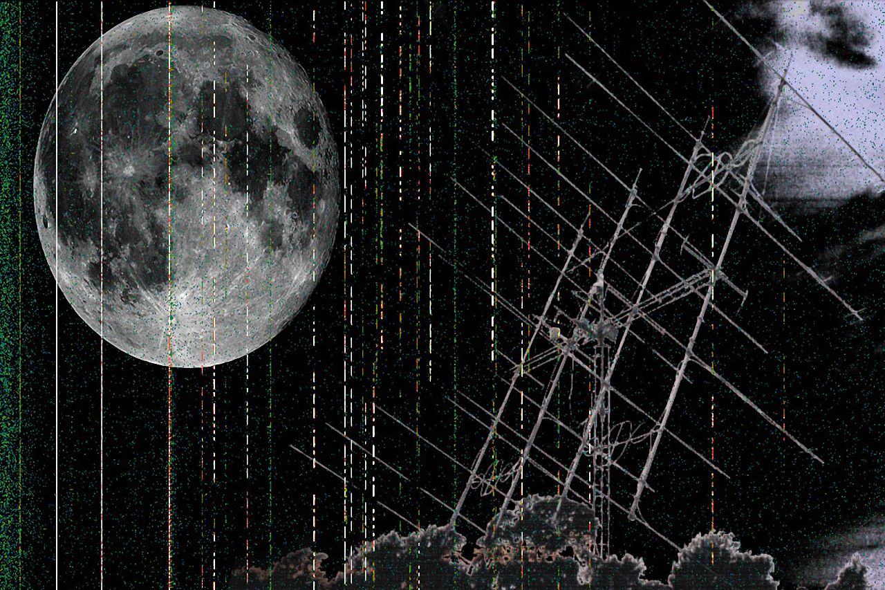
Amateurs now also have access to a Geo-stationary satellite (Es’hail-2) with an S-band/X-band transponder and having a very large footprint covering Europe, Asia, and Africa. Another very interesting field of ham radio activity is Earth-Moon-Earth (EME) communication. The moon is used as a passive reflector to bounce back radio signals back to earth. EME is a very interesting and challenging activity…. Read More.
 Interactive Forums
On this website, we have set up a very comprehensive, interactive discussion forum. It is a moderated and structured forum with multiple boards and categories in line with the topics covered on this website. This is a place where every visitor, member or patron can interact, discuss and express themselves.
Our effort is to foster healthy discussion amongst members in matters related to amateur radio and radio communication science and technology in general. Questions and queries can be made by those who wish to seek information. These will either be answered by the peer group in the course of discussion or by the panel of experts. Article or post requests on specific topics made via the forum will also be taken up.
After a simple registration, members will gain full access to the forums for the purpose of posting. However, any visitor who chooses not to register will still be free to browse the forums. Please check it out… Read More.
 Newsletter Updates
To make it simple and easy for you to stay abreast of the new developments on this website, we have started a weekly newsletter service. This will facilitate easy tracking of new posts and articles. The newsletter will inform you about the latest articles, posts, and share with you other useful information on a regular basis. Strict confidentiality is assured for the mailing list subscribers. Under no circumstances, your email address will ever be shared with a third party.
Those who wish to subscribe to the newsletter can do it by filling out a simple registration form which is accessible on the sidebar of all article and post pages of our website. At any point in time should you choose not to receive our newsletters anymore, you will be able to unsubscribe by clicking on an unsubscribe link.

