

The Center-fed Half-Wave Dipole Inverted V Antenna
The performance characteristics of an Inverted V antenna is not too different from a horizontal dipole. Therefore, I will not repeat what we have already discussed in the article titled The Ubiquitous Dipole Antenna. Readers are requested to read the article if they wish because practically all the concepts and features discussed in relation to a standard dipole are also applicable to the Inverted V. There is a general belief that a dipole antenna will typically produce a set of bi-directional radiation lobes in the azimuth plane, whereas, an Inverted V pattern will be nearly omnidirectional. This belief is certainly true for these antennas in either free-space or those deployed very high above the ground, but might not so much be, in the case of most of the typical and practical amateur radio antenna installations. This is one example of the many myths that prevail. We are going to bust some of them in this article and try to put matters in perspective.
The truth is, in the case of most real-world HF band amateur radio antenna deployments, especially at 20m or lower frequency bands, whatever performance difference one might have expected in comparison to a textbook style antenna installation, progressively starts to diminish on the lower HF bands or at low height above ground. As a consequence, both the standard dipole as well as the Inverted V generally begin to behave in a fairly similar manner. The distinction in their lobe patterns and most other characteristics including the gain begins to get blurred.
A Brief Synopsis of the Antenna Features & characteristics
In this article, I will try to cover various aspects of the half-wave resonant Inverted V dipole antenna including, its geometry, characteristics, performance parameters, the influence of practical surrounding environment where the antenna might be deployed, as well as transmission line interfacing. In addition to all the variables that are applicable to a dipole, the Inverted V has to also account for the Apex angle variation from one installation to another. This is the angle that eventually determines the slope of the Inverted V dipole elements with respect to the horizontal. Take a quick look at the summary below before we proceed further. The indicated Power Gain is TX mode gain that factors in the overall Radiation Efficiency of the antenna installation. RDF stands for Receive Directivity Factor and it characterizes the antenna receive performance. Radiation efficiency takes into account all structural losses and also ground reflection and absorption losses when applicable.
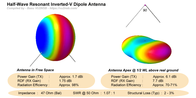
Going by the above summary, it is quite evident that a Half-wave Resonant Inverted V Dipole is potentially a good antenna that offers high radiation efficiency and also a substantial gain. Despite all these positives, most Inverted V installations that fail to deliver satisfactory performance are usually due to recklessly and thoughtlessly carried out installation and deployment.
We will try to find the reasons as to why the performance of a fairly good antenna like the Inverted V, so often, tends to get compromised and what could be done to mitigate these issues.
Half-Wave Resonant Inverted V Dipole Antenna Geometry
An Inverted V antenna has a fairly simple structural geometry. As noted before, it is just a variant of the standard horizontal dipole. The Invertd-V antenna is a center-fed dipole antenna with the feed-point that is at the highest point of the structure. From this central feed-point location, the two arms of the dipole slope downwards at an angle with the endpoints being closer to the ground level. The angle formed between the two sloping wire elements at the apex point is an antenna design parameter that is designated as the Apex Angle. One might note that a standard dipole is actually a special case where the Apex Angle is 180°.

A diagram of a typical half-wave resonant center-fed dipole Inverted V antenna. An important factor to keep in mind is the need for a balanced-to-unbalanced impedance transformation mechanism at the antenna feed-point when fed using a coaxial cable. This is important to attain optimum performance.
Meanwhile, we need to know that although the technical specifications of a standard dipole in free-space (or very high above the ground) would indicate a marginally higher gain in comparison to an Inverted V under similar conditions, let us understand that despite the lower gain, an Inverted V might not be an inferior choice. Both the standard Dipole as well as the Inverted V are typically fixed and non-rotatable antennas, especially on HF bands under practical amateur radio deployment conditions. This is especially true for the HF radio bands with a wavelength of 20m or more.
If and when a Dipole is installed at a height of at least 1 λ or preferably even more above ground level, it might perhaps boast of a slight additional gain at the tip of the lobes on the broadside of the antenna, however, as we look in other directions, the gain begins to drop till there are notable nulls along the wire in the end-fire direction. On the other hand, though the broadside peak gain might be marginally less in the case of the Inverted V antenna, the drop in gain as we look around the azimuth is relatively much less. The end-fire direction nulls are obliterated to a considerable extent. However, this may not be entirely true when either a Dipole or an Inverted V for HF bands might be installed at far lower heights as found in the case of a large number of amateur radio installations. Under these circumstances, both these antennas behave quite similarly.
As a consequence of the above, an HF band fixed oriented Inverted V antenna is likely to offer a far more pleasant overall day-to-day performance in comparison to a standard dipole. Keep in mind that unlike a point-to-point fixed radio communication circuit where a dipole could be carefully oriented to leverage optimum performance, amateur radio requires one to listen and work other stations that might be located along any azimuth direction. Therefore, a non-rotatable antenna would definitely benefit from the relatively better (shallower null) azimuth pattern attributes of an Inverted V antenna.
The Inverted V antenna is a good antenna. Don't dismiss it as trivial... A carefully and thoughtfully installed Inverted V antenna can turn out to be a good station asset. Just as in the case of a standard dipole, an Inverted V antenna can be designed to be either a mono-bander or a multi-bander.
Typical Inverted V Antenna Characteristics & Performance
The basic trend of the characteristics of an Inverted V antenna is more-or-less in line with that of a typical standard dipole. Therefore, I will not dwell on the in-depth explanations of the specifications, parameters, and characteristics that are common. Please find more information in my article on dipole antennas titled The Ubiquitous Dipole Antenna. In this article, I will keep the narrative focused on the unique and special characteristics of the Inverted V antenna.
Most of the differences in characteristics arise due to the sloping elements of the Inverted V antenna. What are the effects of sloping of wire elements? Let us examine.
All the differences in characteristics are proportionate to the magnitude of the Apex Angle. The more it deviates from 180°, as in the standard dipole, the greater are the behavioral deviations. Of primary importance, there are four characteristic attributes that deviate with alteration in the Apex Angle. We already know one of them. It is the radiation lobe pattern that we have been discussing so far. There are three more. Let me list out all four of these deviations below before we begin to look into them one by one...
- The radiation pattern changes preventing deep nulls to allow better azimuth coverage.
- Marginal reduction in peak gain with the reduction in Apex Angle.
- Increase in antenna resonant frequency with lower Apex Angle thus requiring slightly longer element lengths
- Variation in feed-point impedance thus affecting lowest attainable SWR with change in Apex Angle.
Take a look at the table below that illustrates the typically expected variations in various performance characteristics with the alteration of the Inverted V antenna Apex Angle. Please note that in all the cases of Inverted V listed below, the antenna apex point height above ground has been maintained constant at 1/2λ. Only the slope of the elements change in each case with the change in Apex Angle...
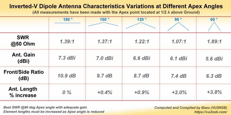
The table summarizes the variations in a few important parameters that influence the general performance of various Inverted V antennas with different apex Angles and deployed at practical heights above the ground level. This table also busts several popular myths about Inverted V antennas in comparison to Dipoles.
Let us summarize what we see above. We have compared five different scenarios. This includes one horizontal dipole (180° apex angle), and four Inverted V configurations with different apex angles ranging from the nearly horizontal 150° to 60° at the other extreme. We examined and tabulated four performance parameters of the antenna in relation to the apex angle variations. All the antennas are assumed to be deployed under similar environmental conditions and installation heights.
1) SWR & Feed-point Impedance: The dipole has a feed-point impedance of approximately 72Ω and hence the best possible SWR (@50Ω) would be around 1.4:1. However, as the apex angle is reduced from the 180° of a dipole, gradually to lower angles, the feed-point impedance of the antenna (which has now turned into an Inverted V) begins to drop. Hence, the SWR starts dropping too, till the feed-point impedance reaches 50Ω. This happens at an apex angle of around 90°. The SWR is now 1:1. Further reduction in apex angle below 90°, reduces the feed-point impedance further. As a consequence, the SWR begins to rise again due to the increase in an impedance mismatch. At apex angles below 60°, the SWR shoots up quite rapidly as the feed-point impedance drops drastically.
2) Antenna Gain: If one were to compare the obtainable gain of a dipole with that of Inverted V antennas at various apex angles, one would realize that there isn't much difference between them. For instance, in comparison to a dipole, the peak gain of a 120° Inverted V is approximately only 0.7 dB less, while for a 90° apex angle Inverted V the gain reduction is only about 1.2 dB... BTW, the values cited above are theoretically ideal installations. In reality, the difference might get reduced even further due to extraneous reasons.
3) Front-to-side Ratio (Side null depth): When it comes to the famous figure of 8 azimuth lobe pattern of a dipole, as against a nearly omnidirectional pattern achievable with an Inverted V, we often come across a lot of confusion amongst a sizable section of the amateur radio community.
Oh! but, isn't it true? That's what we find in the textbooks... Sure, the textbooks indeed say so. They are right, however, our interpretation is usually too simplistic. We tend to ignore the conditions under which the classic figure-of-8 dipole pattern applies. We often tend to assume that the figure-of-8 applies under all conditions of installation and deployment of a dipole. This is a fallacy. It is absolutely true that a typical horizontal dipole in free-space or at a good height above ground level (AGL) will produce a textbook type figure-of-8 azimuth lobe pattern. The depth of null on the sides (end-fire direction) will be quite sharp and might typically be as deep as -40 dB to -50 dB if not more.
All good so far... We all know that any horizontal antenna that is installed at a low height above ground level tends to radiate more at higher elevation angles and the azimuth pattern gradually starts becoming less directional as the nulls begin to become shallow. Lowering the height beyond a point would ultimately lead to a Near Vertical Incidence Skywave (NVIS) antenna.
However, the million-dollar question is how low is low? How high above ground should the antenna be for acceptable all-round performance including reasonable DX? The casual general answer would be, the higher the better, especially in the HF radio context. Although there is no hard and fast rule to determine the acceptable height, quite often for most amateur radio communication work, 1/2λ AGL is considered fairly acceptable, unless one wants to optimize the antenna for extreme low Takeoff angle (TOA) DX. This height of 1/2λ AGL, typically provides a nicely shaped primary elevation lobe which is broad and yet has a reasonably low radiation TOA that ensures good overall performance. Moreover, barring the upper HF bands like the 15-12-10m and VHF/UHF, the HF band antennas at 20m or lower, in the case of a typical amateur radio station, might not make it practically feasible to install them at heights far more than 1/2λ AGL. If we translate 1/2λ to absolute heights in feet (mts.), then we find that at 20m it is 33 ft (10 mts.), while at 40m it is 66 ft (20 mts.), and so on.
For a vast majority of radio amateurs around the world, it is often a struggle to install antennas at very good heights above ground level, especially the wire antennas for which one wouldn't normally erect dedicated tall towers. Height of 30-40 feet AGL is typically the average amateur HF dipole antenna height in most cases. Another factor to keep in mind is regarding antenna installations on buildings in urban and suburban areas. For instance, one might put up a dipole at 15-20 feet on top of the terrace of a tall building (say 50 ft.) and then expect the antenna to perform as if it was 65-70 feet high would be totally mistaken. It would be a mythical assumption. Such a building will invariably have sufficient steel rods embedded in its concrete roof along with additional horizontally laid water-pipes and electric cables to make the terrace surface on top of the building to act as an efficient secondary ground for the antenna that is only 15-20 ft above it. For most practical purposes, this antenna is most likely to behave like one that is installed at 15-20 ft AGL... To find out more on this, check out my article titled Urban Antenna Height above ground – Facts & Myths.

Comparative evaluation of the azimuth section of the radiation lobe patterns of a typical half-wave center-fed Dipole with an Inverted V antenna (90° apex) under two different conditions. One slide in the animation shows patterns for antennas in free-space, while the other shows the results for the same antennas at 1/2 λ AGL. Note the remarkable loss of side null depth when a Dipole is deployed at practical heights above ground.
In one instance, we take the textbook case where both the Dipole as well s the Inverted V are deployed in free-space or very high at many wavelengths (λ) AGL. Here we see that the dipole azimuth pattern features very deep side nulls and thus produces the figure-of-8 pattern as our textbooks tell us. On the other hand, the Inverted V in free-space does not produce those deep nulls. The pattern is more like a rounded rectangle with very minor dips on the sides.
In the second instance, as depicted on the second slide, we have deployed both the dipole as well as the Inverted V at practical heights of 35 feet AGL. Voila!... The figure-of-8 dipole azimuth pattern goes for a toss. It now appears to be fairly similar to the Inverted V pattern with slight extra depression on the sides. However, in the case of the Inverted V, it has made negligible difference to its azimuth pattern which remains almost similar to what it was in free-space. The Front/Side Ratio (Null Depth) in the case of the dipole is about 10.9 dB and for the Inverted V, it is 7.4 dB. The difference in the Null depths is only 3.5 dB which doesn't really mean much.
The bottom line is that unless the wire antennas are installed at very good heights above ground, for most practical ham radio antenna installations there is very little likelihood of noticing any perceptible difference in the azimuth performance between dipole or an inverted V. This becomes more and more true as we switch the band from 20m to 40m and below. Do not be obsessed with one type of antenna over the other. It really does not make any significant practical difference at practical heights. Feel free to deploy your dipole either horizontally or as inverted V. It won't hurt either way.
4) Antenna Length (variation with apex angle): Before we conclude this section of the article, it might be worthwhile in mentioning that the element lengths of an inverted V are always a bit more than that of the horizontal dipole. The magnitude of increase in length will be determined among other things by the apex angle of the antenna. The lesser the apex angle, the greater will be the required length of the element wires. The expected increase in length with the apex angle is tabulated in the chart above. At 120°, it is around +1% while at 90° it is about +2%. At lower apex angles, longer lengths are needed, however, apex angles much below 90° is not recommended unless there is no other option. While installing an antenna, always start with a longer length than what is calculated. Thereafter, one could trim it down to the requisite length.
All over the Internet you will find tons of posts and articles that might tell you that the length of the Inverted-V antenna element is typically around 2-5% shorter that that of a horizontal (Flat-top) dipole. There are also a few Dipole/Inverted-V antenna length calculators on the web that also do the same... Sadly, some of these websites rank at the top of search engine results of Google, Bing, and others. Many old and new amateur radio operators rely on these resources to build their wire antennas, but eventually end up creating a mess... Unfortunately, the claim that an Inverted-V element length is shorter than that of a flat Dipole is utter nonsense. This reckless misinformation is been doled out since many years, unabated..
Does Inverted V produce both Horizontal & Vertical Polarization?
Despite the fact that many radio station operators tend to believe it to be true, the categorical answer is a BIG NO!... A symmetrical Inverted V antenna that is a variant of a center-fed dipole with equal element lengths which are sloped downwards at equal and symmetrical angles from the apex point will always produce only horizontally polarized signal.
The exception would be if the inverted V is installed with asymmetric slope angles with respect to the horizontal. In other words, if the two sides of the dipole are drooped down w.r.t. the horizontal at different angles, then the polarization will become Oblique to an extent determined by the angular asymmetry. Similarly, another exception is an asymmetric wire antenna like the OCFD. In this case, despite the symmetric angle of slope on both sides, the antenna will produce Oblique polarization.
Here is a fun fact that many of us might be unaware of. There is hardly any amateur radio literature both on and off the internet web space that speaks about it. IF the slopes of the OCFD antenna that might have been installed with sloping elements is made asymmetrical so as to ensure that he end-points of the elements form a horizontal line, then the polarization will be horizontal.
I won't go into mathematical derivations to validate the above point at this juncture, however, here is the thumb rule... Draw an imaginary line between the end-points at both sides of the wire antenna. The orientation and the angle of an imaginary line passing through the two end-points of the wire antenna will determine its polarization. A geometric plane that would pass through the above-cited line and the propagation vector (direction of propagation) will fully determine the plane of polarization of the propagating wave.
BTW, there is nothing as mixed polarization. It is just a layman's way of describing the oblique angle polarization. In reality, linear polarization may manifest as either horizontal, vertical, or oblique. In the case of oblique polarization, for the purpose of mathematical analysis, the oblique vector may be split into a set of vertical and horizontal vectors. However, the split vectors are merely a mathematical notion.
Influence on Performance due to Deployment Environment
As we noted in the earlier parts of this article, it is true that a dipole and an inverted V in free-space would perform differently with significantly different all-round coverage. However, we, the radio amateurs in our day-to-day life would usually deal with these antennas under realistic deployment conditions. As a consequence, an inverted V antenna might behave as a very close cousin of a horizontal dipole when installed at low and medium heights above ground level.
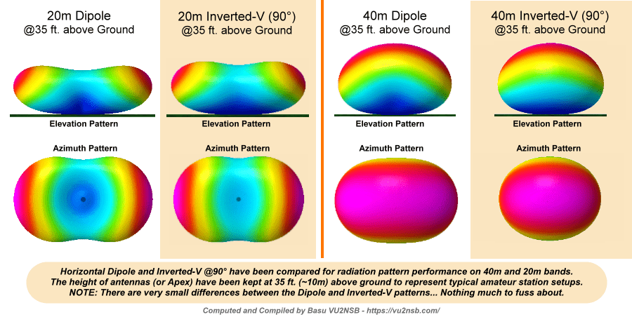
Since a picture is said to be worth a thousand words, I will leave you with the following pictorial chart of the simulated radiation pattern of both the dipole as well as the inverted V installed at 35 feet AGL. The depicted radiation patterns display both the azimuth and the elevation planes sections of the 3D radiation pattern for 20m and 40m HF bands. Just see how similar both the antennas are. Check it out...


(28 votes, Rating: 4.71) - Please vote the article with your valuable star rating. Thanks! Basu (VU2NSB)


SSN SSNf(10.7) – Real-time Solar Data


