

Understanding Antennas – What makes them good or Bad?
Yet I concede that the operator’s experience with a specific type of antenna may indeed be either good or bad. However, this does not necessarily mean that the fault lies with the antenna. More often than not it is the operator’s judgment in selecting the antenna or the way it is deployed that makes all the difference. Unless the antenna in question is technically a poor design that does not allow effective radiation to occur or the structural material used for fabricating the antenna leads to high loss resistance in comparison to its radiation resistance, there is no reason why the antenna will not be able to do the job that is delegated to it.
So, if this is indeed the case, then why do some antennas perform marvelously while others don’t? … This is exactly what I am going to address in this article. Before we proceed, let us distinguish between an antenna per se and a complete antenna system. I contend that antennas are usually not bad or good, but the antenna system as a whole might very well be good or bad. What is the difference between the two? … An antenna is the bare-bone radiator including all its elements, both active and passive. Whereas, an antenna system includes not only the antenna but also its transmission line feeder network as well as the ecosystem under which it is deployed. It is very important to understand this distinction for us to appreciate what we will discuss hereafter.
Let us understand that antennas may on one hand be either suitable or unsuitable for an application. On the other hand, they may be convenient or inconvenient to use. Whereas, the antenna systems could be efficient or inefficient on one hand, while on the other hand, they may be good when deployed with care and due diligence but might be bad or even terrible if not deployed properly.
The bottom line is that most of our antenna woes are not due to the antenna itself, but more often due to our lack of understanding, poor choice of antenna for the application, and even more due to not enough thought being put into the optimization and selection of the installation and deployment environment.
Antennas – Suitable or Unsuitable
Let’s begin by saying that all types of antennas are not suitable for every communication application scenario, neither are they always suitable for every deployment environment. I will try o explain this with a few simple examples.
Quite often it is the radiation pattern of the antenna that determines whether it might be suitable for a particular job. Although the radiation lobe shape, especially the elevation angle is often determined by how and where we install the antenna, the inherent lobe pattern geometry of the particular antenna also plays a vital role. For instance, the antennas with high takeoff angle lobes will radiate a large part of the RF energy at higher angles towards the sky thus making them far more suitable for short-skip medium range communication on HF bands using ionospheric reflections. This will in turn, under most circumstances result in compromised long-distance DX performance because the energy radiated at low angles that is required for log-skips will be much less.
Secondly, a typical antenna may be either vertically or horizontally oriented resulting in vertical or horizontal polarization respectively. Both the geometric orientation as well as the ensuing polarization might adversely or favorably affect the communication performance. For, instance, a vertical antenna will usually produce a fairly deep null in the vertical direction at 90° takeoff angle. As a consequence, due to the tapered shape of the radiation lobe geometry, the gain of the antenna at a high angle would be rather poor. It means that vertical antennas might be relatively poor for short and medium range HF radio ionospheric skip communication. However, the Surface wave (often termed as a Ground wave) propagation at the lower HF frequency bands might get enhanced due to a longer range surface wave coverage with vertical polarization compared to horizontal… That’s not all… A vertical antenna might be noisier than a horizontal antenna and hence be susceptible to higher local area QRM at the receiver.
Therefore, as we see, the suitability of an antenna would depend on several factors. OK, the above example was about vertical antennas. How about horizontal antennas? … Well! They too have their idiosyncrasies. Firstly, compared to the vertical antennas that usually have their integral ground plane system and have better inherent low takeoff angle performance, the horizontal antenna will typically depend on its relative position above ground to determine its takeoff angle. Not only will the number, position, and angle of radiation lobes in elevation vary due to the ground, but in the case of horizontal antennas, at certain specific heights of deployment, the antenna will radiate a significant amount of RF energy vertically towards the sky. It could be considered a waste of energy if the antenna is meant for DX communication. This would occur at integral fractions of wavelengths above the ground like 3/4λ for example.
Then again, there is another common misconception amongst many amateur radio operators that a bigger gain and a larger antenna is guaranteed to provide better performance over a simpler lower gain antenna. However, that’s not how it always works. It will depend largely on the deployment conditions. A larger (higher gain) antenna may not always be suitable when either the real-estate or other limitations might exist. A simpler antenna might be more suitable as it might, at times, outperform the larger antenna. Please read my article Why might Antenna Height matter more than Gain for detail explanation.
Within the horizontal antenna family, some antennas might be noisier than the others. For instance, a horizontal dipole or a Yagi might be noisier than a delta loop or a cubical quad. This is because the dipole or Yagi elements are open-ended with endpoints that spaced far apart. As a consequence, the static noise on these antennas is higher. Why are we emphasizing antenna noise? That’s because it is a factor that influences the net performance of the radio station. For the same magnitude of RX signal, if the noise is higher, then the signal-to-noise ratio (SNR) becomes poorer. In other words, the ability of the antenna to effectively present a readable signal to the receiver diminishes resulting in reduced station performance.
Let’s move on to other examples to show how one antenna might be suitable under a specific situation while another might not. Let us now turn our focus to VHF/UHF radio. Though horizontally polarized antennas are used for SSB, CW, and other related modes, it is a standard practice to use vertical polarization for FM VHF/UHF use. FM is a popular modulation mode for VHF/UHF short-range communication within city limits. Both radio amateurs and other services extensively use VHF FM radio. They might be base-stations with antennas installed at better heights above ground or they might be vehicle-mounted mobile radios or handheld (HT) portables.
In almost every mobile or portable scenario within city limits, the problems posed by urban clutter due to buildings and other structures are at times pretty ominous. The radio signals at VHF/UHF are unable to penetrate well enough through multiple blocks of buildings. Therefore, the only viable propagation mode from one part of a large city to another is typically through the phenomenon of diffraction over the top of buildings along the city’s skyscape. Check out my article Terrestrial VHF Radio Signal Coverage – LOS for a detailed discussion on this process.
Now, take a look at the illustration below that highlights the role, suitability, and choice of the antenna under the circumstances cited above. Antennas on vehicles or HT portables operated at the street level or anywhere that is at a far lower height than the surrounding buildings (obstacles) must not be the low takeoff angle antennas.
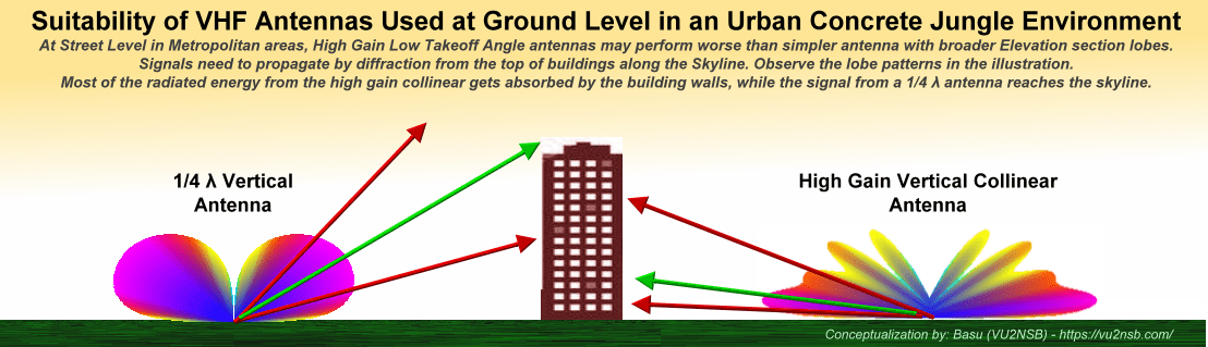
The illustration attempts to depict the situation where VHF mobile antennas mounted on vehicles that operate in a large city. The objective of this illustration is to show the difference in radiation takeoff from two different types of antennas. The Vertical Collinear antenna has higher gain but lower takeoff angle in comparison to the other antenna, a quarter wave vertical. Although the higher gain V-Collinear would be most desirable for long range coverage if it had been installed a a good height above the city skyline, but since intra-city VHF communication relies largely on diffraction from top of buildings, the quarter wave vertical with higher takeoff angle may be better suited within the city for mobile or portable radio at street level.
In the event of poor radio contact or the inability to do so, the general tendency is either to increase the TX power or to opt for a higher gain antenna. The increase in TX power works to our advantage, while increasing the antenna gain in a typical mobile or portable environment may turn out to be counterproductive.
The reason for the unsuitability of higher gain mobile antenna used in the urban concrete jungle is that these antennas would need to remain omnidirectional and yet produce more gain. This is only possible if the radiation lobe is vertically compressed to produce a flatter donut shape. As a consequence, we get a higher gain from the antenna but the takeoff angle is low with most of the radiated energy concentrated at lower elevation angles.
Isn't that what we always wanted? Everyone says that a low takeoff angle is great for longer range communication. Isn't it true? Wouldn't higher gain low takeoff angle antennas like vertical collinear be better? ... Well! Not always... At least, not in our present scenario.
When a low-angle, high-gain antenna is installed at a good height above ground to have a reasonably clear view of the horizon, it does wonder. It is every DXer's dream. However, in our situation when the antennas are nearly at the street level and surrounded by tall buildings, it changes the dynamics completely. The above illustration is self-explanatory. Most of the RF energy emitted from the Vertical Collinear (low angle) antenna strike the surrounding buildings. In an effort to penetrate through multiple concrete and brick walls that fall in the way, the signal attenuates rapidly and is lost. On the other hand, a relatively lower gain but moderately higher takeoff angle antenna like a simple 1/4 λ Vertical antenna would beam most of its radiated energy at higher angles. As a consequence, a significant part of the TX power will reach the top of a nearby tall building. Thereafter, the signal will diffract around the edge of the rooftop to continue on its journey through the air to reach the other end of the communication circuit... This works!
To summarize what we discussed so far, it must be appreciated that all antennas are not suitable for every application. Even though a particular type of antenna might possess higher gain and other superior characteristics, it may not be suitable for all applications. The suitability depends entirely on the task at hand. We need to eventually make an informed choice.
Antennas - Convenient or Inconvenient
The next factor that needs attention is whether an antenna is convenient or inconvenient. This can be rated in several ways. Is it structurally inconvenient? or Is it operationally inconvenient?
Structural inconvenience might lead to a situation when it could be difficult to deploy it due to its size and shape. It may be more convenient to deploy some type of antenna at a specific location, while other antennas might be very difficult or inconvenient. Similar inconvenience may be extended to directional antennas under many situations. They need to be mounted on an elevated tower/mast along with a rotator. This requires enough clear space in all directions. There could also be other logistical issues related to the installation of the tower, etc.
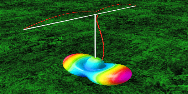
This is an example of a relatively inconvenient antenna to set up for a radio amateur who might not be experienced. Unlike far more convenient antennas like the dipole, inverted-V, etc that could be simple plug-n-play, the antenna in the illustration is a multi-band Doublet that needs to be driven using a balanced line for a substantial length. The overall installation is more complex to achieve optimum results. This image shows not only the antenna but also the current distribution along the element and the transmission line. The radiation lobe pattern is also presented.
Therefore, many wonderful antennas that fall in this operationally inconvenient category require the station operator to acquire a deeper understanding of antennas before they could use them. However, it does not mean that these antennas are bad or poor performers... It is just that they might be operationally inconvenient for an amateur radio operator who does not wish to invest some time in familiarizing and learning more about them.
A few examples in question might be a Doublet antenna or a multi-band W8JK bi-directional antenna. These antennas are superb antennas providing excellent performance but they require to be installed with care. It is not just the antenna, but also the associated transmission line that collectively forms the antenna system. Unlike a regular antenna with quickly hooked up coaxial cable, these setups need far greater finesse in their handling and deployment. For instance, being non-resonant multi-band antennas, the SWR on the transmission line will almost always be quite high. That's perfectly fine, as long as we have a very low loss transmission line. The SWR by itself is usually not a problem. It is the cable loss factor that is mostly the issue... Contrary to popular belief, the SWR on its own, is never really an issue. We can have wonderfully performing antenna systems with high SWR existing on the transmission line as long as the line has low inherent attenuation characteristics, and is able to handle the required voltage and current.
To mitigate or almost nullify the adverse effects of high SWR, the transmission line has to be a very low loss type parallel open-wire line. However, such transmission lines come with baggage. They cannot be turned, twisted, or rolled the way one could do with coaxial cables. They also cannot be routed randomly via holes, conduits, or along the walls or floor of the buildings. None of these are acceptable. The open-wire RF transmission lines must be spaced well away from all objects including walls, etc. They cannot be taken around sharp bends. They need a large radius to change the orientation. Thereafter, these antennas would require a good balanced ATU near the transceiver end. Conforming to these requirements is not everybody's cup of tea. Many who have attempted these antennas without enough due diligence or studying about their operational dynamics have ended up with poor performance, even though these antennas are amongst the finest antennas.
Some of the modern and over-simplified variants of another great wire antenna, the G5RV, the way they appear all over the internet have got it completely wrong. They tend to advocate the use of coaxial cable runs directly from the G5RV antenna feed-point. The G5RV antenna, like the other antennas I cited above also non-resonant on most bands. As a consequence, as in the original design, it requires a low loss open-wire or a window-line, but certainly not a coaxial cable. Most of the authors of the coax variant G5RV claim that they could get a manageable SWR at the transceiver... Oh Yes! ... Sure, they did. They reduced SWR that one might find at the TXR end with long runs of coaxial cable from the antenna is due to the excessive cable losses. A coaxial cable loss of unreasonably high magnitude serves no purpose. What's the point of achieving a reasonable SWR at the TXR end if most of the TX power is lost as heat on the long coaxial cable? Think about it...
So, as I said before, there are convenient antennas that can be set up and run without much fuss while there are other antennas that might appear to be inconvenient at first to the uninitiated, but they are great antennas and are a pleasure to work with.
Antenna Systems - Efficient or Inefficient
So far we have discussed the antennas in isolation. Now, let us turn our focus to complete antenna systems that also include the transmission line, any other feed-point or TXR end interface circuits, etc. Although, As I said before the antennas on their own are not good or band they are mostly all good. However, the antenna system as a whole could indeed be good or bad (or maybe poor is the word). A poor antenna system is usually the fault of the one who set up the system.
Before we go into good or bad, let us briefly take a look at why some antenna systems are more efficient than others. The reasons that result in antenna system inefficiency may often be a part of the set of attributes that determine whether, on the whole, the system is good or bad.
Antenna system inefficiency may stem from a variety of factors. Some of the major ones being the incorrect choice of structural material, undue proximity to earth's surface or other RF energy-absorbing materials and structures, or having a significant impedance mismatch at the antenna feed-point if driven by a transmission line that produces considerable loss at the frequency of operation.
Many operators who use an impedance matching unit like an ATU in the shack tend to get a false sense of relief as they often believe that a low SWR obtained after using the ATU would have corrected all impedance mismatch issues. Unfortunately, this is far from true. The SWR on the transmission line leading to the antenna along with the associated power losses that existed before the use of the ATU would continue to remain unaltered even after one uses the ATU to make the transceiver see a good !:1 match... The ATU does not solve the core problem. It only makes the transceiver believe that everything is hunky-dory, whereas it is not. The problem can only be solved by addressing it at the antenna system design level.
The inefficiencies due to transmission lines and associated SWR can at times grow to unacceptable levels. At HF radio frequencies, very often we get away with it especially on the lower frequency bands, but on VHF/UHF the coaxial cable transmission losses may become a deal-breaker unless the antenna system is designed with care. Remember, the higher the frequency, the higher are the cable losses... The worst thing is that high cable losses often camouflage their ill-effects by creating an illusion of low SWR at the transceiver end of the antenna system, thus making many unsuspecting radio amateurs to falsely believe that all is well. This is one of the examples of many pitfalls of misinterpretation of measurement results in radio communication. Check out my article Will low SWR always ensure a good Antenna setup?. In that article, I have dwelled on this subject in greater detail.
In the Near-Field region of an antenna also known as the induction region, then the RF energy has yet to get fully transformed into electromagnetic (EM) waves. In this proximity region around the antenna, the presence of any other object with conductivity and dielectric constant that is conducive for signal absorption and/or re-radiation usually begins to distort the antenna characteristics at best or play havoc at worst. This is why one has to be conscious of sufficient clearances around the antenna structure. At least 1/2 λ or better still up to 2 λ distance around the antenna should be clear of other objects like buildings, walls, rooftops, floors, pipelines, overhead or buried wires, etc including the underlying earth's surface. At VHF/UHF bands, this requirement might be trivial due to short wavelengths, but it may grow into a nightmare on HF bands, especially, the longer wavelength top bands. The interaction and RF absorption of such objects near the antenna may contribute significantly to its inefficiency and under-performance.
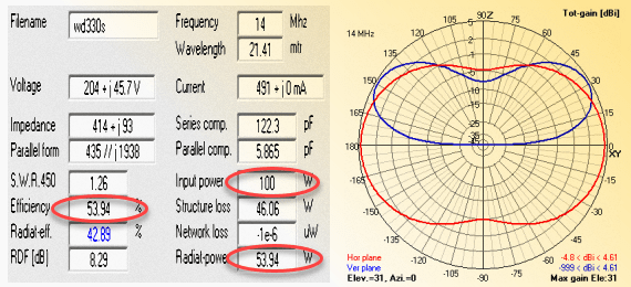
This is the example of a well known broadband HF wire antenna of the T2FD type. The antenna structural losses, overall efficiency, radiation efficiency, etc are all depicted for this real-world antenna. The antenna is deployed for 20m HF band and is placed over an average quality city ground with the soil conductivity and the dielectric constant made quite similar to what one might expect in an average modern city.
Most of the practical problems faced by amateur radio operators on the HF bands during low SSN may be attributed to their poor radiation performance at low takeoff angles. This is caused primarily due to the low height of the antenna above ground. Those who install antennas on top of tall buildings are often misled to think that they could consider always the height of the building as a part of the overall antenna height... Although the building height can be leveraged to our advantage in some cases, it may not always be the case. Therefore, take the additional building height with a pinch of salt. You could find out more on this in my article titled Urban Antenna Height above ground – Facts & Myths.
Another factor that is perhaps one of the most obvious causes of antenna system inefficiency is structural loss. This could be due to poor choice of material including either or both the conductive elements of the antenna or various insulating materials needed to support the antenna structure. Losses in elements, as well as losses due to energy absorption in insulation, add up to play an unwelcome role in determining the overall antenna system efficiency. When the equivalent loss resistance component of the antenna impedance begins to grow and becomes significant in comparison to its radiation resistance, the efficiency begins to fall. Other forms of losses on various accounts like the transmission line loss per unit length, additional compounding of these losses due to high SWR on the line, losses in impedance transforming, and matching units like Baluns, ATU, etc all aggregate towards antenna system loss.
Therefore, due to several reasons cited above, an antenna system might be efficient or inefficient for our purpose.
However, the antenna efficiency might not always be a deal-breaker while operating at the typical barefoot power levels as are the norms in amateur radio. Operating at power levels starting at QRP of a few watts to the regular barefoot level of 100-200W doe not pose serious problems. However, at legal power limits of 1 KW or more, it is always prudent to optimize the antenna system efficiency.
How inefficient could an antenna system practically be? That's a million-dollar question... If the inefficiency is caused by ignorance, incompetence, or recklessness of the one who installed the antenna, then I wouldn't even try to guess because it could well be horrendous. On the other hand, a typical, practical, real-world antenna might have efficiencies from as much as 98% to far less.
A decent broadband (multi-band) antenna with several good attributes called the T2FD antenna, including its variant, the T3FD are examples of fairly inefficient antennas, yet they are pretty good. Ah! So, what is the ballpark figure of their efficiency? Well! It could be as low as 50% at some of the frequencies, implying about 3 dB loss... OMG! ... Doesn't it mean that half the transmitter power is lost and only half of it is radiated? Yes, precisely, that's what it means... But lucky you, losing half the power is not so significant from the perspective of the typical practical radio communication scenario. A 3 dB loss amounts to just about a 1/2 S-unit reduction in signal strength are the far-end receiving station. This 3 dB loss means little unless you are operating under the most difficult, weak-signal conditions with rock-bottom SNR where the communication link capability is being stretched to the limit. Unless it is this, don't bother...
Remember, if people can live with a (so-called) antenna like the Isotron, which BTW, might have a typical gain as low as -20 dBi, implying that the losses could almost be as much as 20 dB, then losses to the tune of 3 dB might not be a deal-breaker. Just to give an idea of what it could mean, a 20 dB loss would result in barely 1W out of every 100W from your radio station to be transmitted. While receiving, the signal received would be around 3-4 S-units weaker than a typical 1/4λ vertical antenna, or about 5 S-units less than a nicely installed simple resonant wire dipole...
If that is so, then why do these antennas even work? ... The answer is that when HF radio propagation conditions are nicely open, we do not need 100W to establish reliable communication even across DX ranges over several thousand kilometers. We might need only a couple of watts, or perhaps 1W or less, which translates into 20 dB lesser power output from our transmitter. That's how QRP enthusiasts work... The rest of us who run 100W or more, often do it to provide a huge SNR cushion to the communication links and also to continue living with all the shortcomings of our antenna installations without ever needing to take the trouble of correcting them.
The more important factor is the shape, direction, and takeoff angle of the radiation lobes. The reason why some HF amateur radio stations are practically deaf and unable to receive enough signals under difficult low SSN conditions is not necessarily because the bands are dead, but more likely because they ignore this vital factor related to the antenna they use. If we get this aspect right, we could perhaps be able to live with most of the other irritants.
Antenna Systems - Good or Bad
So far, we have examined situations where various antenna traits may play their roles in either enhancing or degrading their performance, but none of them, in my opinion, could be used to classify an antenna as good or bad. An incorrectly chosen antenna might have been improperly used in a situation which perhaps was not its forte, or it might have been poorly and thoughtlessly deployed during installation thus sacrificing its performance capabilities.
The true test of bad or a poor antenna system is to check and see if it might be doing other things that it is not intended to do. For instance, generating EMI/RFI, picking up spurious noise and interference from sources that it should easily have avoided, produce RF feedback through RF current flow back into the ham shack thus disrupting the normal functioning of equipment, etc. All or any of these factors could lead to classifying an antenna system as truly bad.
Unfortunately, at times, some of the antenna systems deployed at the QTH of a radio amateur is done rather thoughtlessly without enough due diligence or installed in a haste without spending enough time to learn and understand some of the essential basic principles. In the modern-day and age, when radio amateurs are served everything on the platter from commercial equipment outlets, the desire to learn more about the antenna and its behavior or idiosyncrasies has taken a backseat. An average radio amateur nowadays takes an antenna for granted. As a consequence, many a vendor of antennas dish out substandard products and get away with it. In the end, it is the amateur radio operator who has to ultimately suffer.
The Good, The Bad, and The Ugly
I have covered most of the factors that could render an antenna system a poor performer in several of my other articles and posts. Therefore, I will simply list some of the more important points below with recommendations along with brief explanations. All these indicators listed here would lead to a basic checklist of factors that might help identify some of the traits of bad or poorly performing antennas...- Unless you have absolutely no option whatsoever, do not fall into the trap of believing that miniature miracle antennas could be of any use other than making your pocket a bit lighter. There are no miracle antennas. They are all scams. Remember, there is no free lunch in the world. Everything needs to be paid off with another tradeoff that might not appear to be so obvious at first, but it is bound to be there.
- Stay away from some of the well known, irrationally small-sized antennas unless you are an antenna expert and know what you are doing. Unfortunately, it would unethical for me to list their brands and types, but remember, if somebody is promising the moon, then it is likely to be a scam. You might also read glowing reviews by some uninformed users, but apply your mind and stay away. These antennas get away due to two reasons... Firstly, as per the famous amateur radio adage, when the HF propagation is very good, even a coat-hanger might work as an antenna. Secondly, the reviewers who found such antennas to be good were perhaps those whose exposure to other truly good antennas might not have been there at all. Hence, whatever these antennas did for them must have provided a sense of euphoria.
- Never fall for the recommendation of an operator who is basing it on his experience while working with ultra-weak signal modes like FT8, etc. The reason is that these digital modes work under conditions of SNR that could be negative 20-25 dB (100-250 times weaker signal) below the regular radiotelephony SSB signals. This implies that if a dubious antenna were to be even 100-250 times worse than an average regular HF antenna, the FT8 user will not even know the difference due to its weak signal handling capability... Discard such recommendations unless you want to restrict yourself to FT8 or other WSJT modes. After all, comparisons only make sense if they are made between entities operating under similar situations and conditions.
- Although it might be unavoidable sometimes due to real-estate limitations, operational, or logistic reasons; but if there is a viable option, do not use End-Fed or highly unsymmetrical antennas. Whenever possible, always prefer a symmetrically structured antenna for best results. For instance, these days almost every other newcomer to amateur radio is seen opting for an End-Fed wire antenna (EFHW dipole, etc) with a high transformation ratio Unun (loosely called Balun). They are wound on ferrite toroids with impedance ratios like 9:1, 49:1, 64:1, etc depending on the wire element length in relation to the wavelength of some of the popular bands. These antennas might be acceptable when there is no other option. Otherwise, stay away from them since they might be recipes for several other problems that one might struggle to mitigate later... After reading this, some people might exclaim, What nonsense! ... However, trust me when I say this... I will leave you with food for thought. If these End-fed antennas are indeed good, then why don't QRO stations running legal power limits, commercial operators, broadcast stations, etc ever use these antennas? They don't, because they are messy antennas with unacceptable imbalances, EMI/RFI issues, radiating feeders, RF feedback, inefficiencies, etc to name a few. At low power levels as in regular amateur radio, these ill-effects get proportionately subdued and hence they appear to be beyond comprehension and detection by an average radio amateur... However, the issues continue to exist, and they compromise the performance in more ways than one.
- Irrespective of whether it is mono-band or a multi-band antenna, avoid choosing those that are non-resonant and also fed through coaxial cable that requires a ferrite/powder-iron core (toroid or otherwise) type broadband Balun or Unun to be used at the antenna feed-point. Unless the antenna is resonant with the impedance being purely resistive, we have a problem... The problem is technical but I will explain it briefly. In the case of a non-resonant antenna feed-point impedance, it is a complex impedance containing both resistance and reactance. This results in a phase-shift between the voltage and the current flowing in the ferrite core broadband Balun. The magnitude of the reactive current component of the total current does not contribute to power transfer. It is a circulating current that may grow quite large in magnitude to begin magnetic field saturation of the core. Under these circumstances, not only could the Balun overheat and destroy itself, but the Balun's impedance transformation also goes for a toss, thus resulting in a gross mismatch. This is a limitation with all such broadband ferrite core based transformers. The air core coils used as transformers do not suffer from this problem but they cannot be made broadband... The bottom line is that although it is perfectly fine to use a broadband ferrite core Balun/Unun with properly resonant antenna systems like the dipole family of antennas, Yagis, Cubical Quads, etc, it is not meant to function optimally in reactive impedance environments.
- A highly asymmetric antenna like an EFHW antenna also has another inherent problem that needs to be addressed. Many of the vendors do not ship them with a counterpoise wire, nor do they actively recommend using one. As a consequence, radio amateurs use the contraption directly out of the box and get on the air... The problem with this approach is that the antenna needs a counterpoise wire element to function but it doesn't have one. Therefore, it piggybacks on to the transmission line coaxial cable that is leading back to the ham shack and treats it as its counterpoise. The outer braid of the coaxial cable serves the purpose. It is like having one end of the antenna to be right inside the shack and that's the worst thing that could happen. Therefore, the solution to mitigate RF feedback issues of such antennas and also to make them behave somewhat like an antenna, they need a counterpoise wire to be attached at the feed-point side of the matching Balun (9:1 or 49:1 or whatever)... With the counterpoise wire, the end-fed antenna would no more be strictly end-fed but begin to resemble a poor, battered distant cousin of a more symmetrical antenna. Some people suggest that one could use an additional choke Balun at the antenna end instead of the counterpoise wire to clear up the RF current feedback into the shack... Do that by all means but not without a counterpoise... The counterpoise is desperately needed for the antenna to function. Do not deprive it of its essentials as it would result in further deterioration of the overall performance of the antenna... The counterpoise wire is the only feasible way to go forward. Make it long enough in relation to the antenna wire length.
- One of the major factors that make an antenna system poor or bad is the improper deployment of the transmission line system. The antenna part of the system should be the one that does all signal radiation and reception. The transmission line must do exactly what its name suggests. It should neither participate as an RF signal radiator nor as a receiving element. For it to function without radiating or receiving, the current flowing in the two wires of the transmission line must be equal in magnitude and opposite in direction. If this equilibrium is disturbed by an extraneous factor, then it no more an RF-tight (as in watertight) line. A current imbalance during TX will cause EMI/RFI all around the neighborhood, while a current imbalance during RX will open up floodgates for noise (QRM) pickup. The difference of current due to imbalance in the line is called Common-Mode Current (CMC). If the termination of the transmission line (the antenna) is not imbalanced, then the possibility of line imbalance also becomes negligible... This is the reason why I have always recommended opting for symmetrically balanced antennas over grossly imbalanced ones. Achieving low QRM pickup characteristics of an antenna system through its transmission line is an extremely important factor. Lower the QRM noise presented at the receiver, the noise floor on the band scope would be lower. This will result in weak signals to present themselves with improved SNR... This is how it should be in a good radio station setup. Remember, unless you can hear the other bloke, you can't work him.
- Finally, let me say that it is a good idea to always use some kind of a Common-Mode Current (CMC) choking arrangement at the antenna end of a coaxial cable transmission line. This is irrespective of what antenna is being used. Of course, in the case of asymmetric antennas like the off-center fed (OCFD), Windom, EFHW dipole, etc, one might need to do aggressive CMC choking due to fairly high magnitudes of CMC. One might need to typically achieve at least 40 dB CMC choking if not more in these cases. check out my article that dwells deeper into various aspects of this topic at Does Coaxial Cable Choke at Antenna cut RF Noise?... Furthermore, I would also suggest that one should not be averse to applying some amount of CMC choking even for balanced antennas like Dipoles, etc. The reason is that although these antennas are theoretically well balanced, in a practical real-world deployment environment, the balance of these antennas may get partially compromised leading to a small but finite amount of CMC on a transmission line. This kind of imbalance occurs on account of geometrical and topographical asymmetries caused by various physical objects and artifacts that are present within reasonable proximity in the installation environment. Due to inductive or capacitive coupling (however small that might be), the antenna would no more remain absolutely balanced. The CMC generated on the transmission line due to these factors should not be ignored, in my opinion. It is an inexpensive proposition to incorporate CMC choking near the antenna feed-point, therefore, why shy away from it.


(14 votes, Rating: 5.00) - Please vote the article with your valuable star rating. Thanks! Basu (VU2NSB)


SSN SSNf(10.7) – Real-time Solar Data


