

100W on a Wire Antenna – Is it good enough for DX?
However, for all this to be viable on a reasonably regular basis, there are a few fundamental prerequisites. First of all, the station operator would need to acquire a fair understanding of how HF band ionospheric propagation works. This is important so that a frequency band with the best prospects of propagation openings for the specific time, and the DX region of interest is known and identified. HF radio is not about randomly picking up the microphone at any time and to call anybody one might like. Unlike VHF/UHF communication where the propagation and coverage range is relatively stable and consistent, HF radio is a different ballgame where the propagation conditions often change drastically on a minute-to-minute basis. One might exclaim, OMG! It’s all so crazy! … Well!, at first glance, it surely seems to be so, however, in reality, there is a method to the madness… In this post, I will try to unravel some of the apparent mysteries of how to use nominal barefoot 100W or less RF power and a simple wire antenna to work the world.
What Modulation Modes are Best with 100W on a Wire?
The short answer is – All modes… I prefer SSB radiotelephony or CW most of the time. Sometimes, I do operate PSK31, RTTY, and few other real-time conversational digital text modes too, but that’s only on rare occasions. To learn more about various conversational and non-conversational digital modes, please refer to my article titled Data & Text Mode digital Radio.
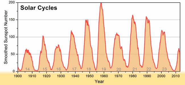
This chart depicts historical occurrences of a number of Solar Cycles from the past. The minima period between Cycle #17 and #18 are of special interest to us as it marks the period during WW2. Yet HF radio communication were carried out constantly.
Unfortunately, the hard fact that people often do not wish to face is that there is not much to be proud of establishing FT8 type contacts on HF when operators run their stations at non-QRP power levels. Anyone who transmits FT8/FT4, etc., at nearly 50-100W or more are grossly misusing the mode. The need to run such high power to establish contacts via these modes is only a reminder of how inadequate one’s amateur radio station setup might truly be. The signal strength reports received from other stations, quite often in negative decibels (-dB) values, serve to rub in the fact that a lot needs to be done by the station operator, not only to optimize his station but perhaps also to learn the nuts and bolts of HF propagation.
Let me reiterate at this point that I am a big fan of the technical brilliance of Joe Taylor (K1JT) and Steve Frankie (K9AN), yet I am a firm believer that the WSJT modes are not cut out for regular use on the HF bands. Those who enjoy these modes while running no more than 5-10W or less are doing good, however, when an operator needs to desperately run 100W or more to establish these contacts, then it surely brings up a red flag. Remember, all these WSJT weak-signal modes are capable of decoding at around -21 to -26 dB, or far worse SNR referenced to 2500 Hz detection bandwidth. While drawing an equivalence to the SSB radiotelephony, this translates 100W on FT8/FT4 (-20/-23 dB SNR) to approximately 10-20 KW on SSB… Hence, if somebody were to now tell me that unless he runs 10-20 KW on SSB, he does not see any prospects of establishing HF radio contacts, then undoubtedly, something must be extremely wrong… Read the related article on weak-signal capabilities of these modes, titled Do Digital Modes like FT8 work Below Noise?
In my view, these ultra-weak signal digital modes are like the Blue Pill of HF amateur radio. Those with performance issues related to propagation on HF bands, or recklessly set up antenna systems, end up with no option but to use these modes on a regular basis. Rather than accepting one’s shortcomings and getting addicted to these Blue Pills, wouldn’t it be nice to naturally enhance the capability and performance of the station so that one could start having QSOs on regular SSB radiotelephony, CW, etc., even during the low SSN conditions?
I am aware that some of us might be skeptical about the possibilities of using the regular radio modulation modes during the low SSN phase… Fair enough! … Let me cite an example to dispel this skeptical notion.
We all know that the 11-year Solar Cycle brings in solar minima at regular intervals. At present, during 2019-2020, we are passing through the solar cycle minima between the 24th and the 25th cycles… Now, let’s go back in history and glance through some of the earlier cycles and see what they meant. For instance, the Solar minima that fell between cycle #17 and #18 occurred during late 1943 and early 1944. As a consequence, the entire 1943 and 1944 were dealing with rock-bottom SSN figures. During this time, WW2 was in its decisive phase with extensive communication requirements of the troops all around the world. Various armies, navies, and air-forces were operating from almost every part of the world. They needed robust communication. VHF was only for short-range, while the satellites did not exist at that time. The onus of the bulk of the communication rested on the HF bands. There were no fancy ultra-weak signal digital modes. All communication was either CW or RT. How did they do it? … Think about it… They never said we can’t do it unless someone provides us fancy digital modes.
If HF radio communication could be sustained even during the sunspot minima phase while WW2 was in full bloom, then why can’t we the radio amateurs of today learn to operate on HF during the current solar cycle minima? Why are we unable to perform without the Blue Pills of HF? Why can’t we gear-up and train ourselves to perform naturally without falling back on the unnatural performance-enhancing modes? … The fact is that it can be done. Maybe we are too lazy and don’t care to train ourselves or learn how to negotiate hostile HF radio propagation conditions… However, in this article, I would attempt to point out a couple of factors that could be managed and optimized to enhance prospects of using the natural communication modes on HF bands.
There are a few things that one might need to improve, or double-check the quality of their station installation, and also to introspect on their own skill sets, especially, those related to the comprehension of a variety of important HF propagation phenomenon.
How to frequently work SSB Voice/CW DX with 100W and a Wire?
Unlike shortwave broadcast stations that need to ensure sufficient signal field-strength at all locations within their coverage area at all times irrespective of propagation anomalies, an amateur radio station works by leveraging the good propagation openings as and when they occur. Amateur radio HF communication is not about maintaining 24×7 robust contact with the destination station on a fixed frequency, but it is about finding and utilizing the most optimum frequency band during any time of the day or night, thus tailoring activity to fall in line with the whims and fancies of mother nature that ultimately determines the propagation conditions.
Having said that, let us now figure out the important things that we should do at our radio stations to attain the objective of optimum communication capabilities.
- The station antenna must be efficient while transmitting.
- The antenna radiation pattern must have lobe shapes and takeoff angle that are optimum
- The common-Mode Current (CMC) on the transmission line must be nil or the bare minimum to ensure the least noise (QRM) pickup from the surroundings.
- The ham shack must be set up with due diligence to minimize extraneous and spurious noise from being picked up by various station equipment. Avoid switched-mode power supplies with inadequate EMI/RFI suppression, and other items like LED lamps, etc that produce broadband noise.
- Operator must have an adequate understanding of the propagation conditions that vary from time-to-time on a band-to-band basis.
Will all these above factors help? … Yes, they will make a world of difference.
Should I opt for a QRO Linear Power Amplifier to increase TX output? … No, under normal circumstances, that’s a pretty dumb thing to do. Remember, no matter how much power you transmit, you can’t work the other station unless you hear him. In all probability, the DX station might not be using a linear PA, and hence would have normal signal strength.
Should I strive for a better antenna or a better rig if I have the resources? … Forget wasting your time and money on the better rig. It will do no good other than adding pounds to your vanity unless you have a damn good antenna system. Therefore, the priority must always be to invest in a better antenna system than a fancier rig.
Should I opt for a new higher gain antenna or should I raise my existing antenna higher? … Unless you can place your larger high gain antenna as high as you might be able to raise your existing antenna, the better option would be to raise your existing antenna as high as possible. The benefits accrued due to a substantial additional height are likely to outweigh the benefits of additional gain obtained without an increase in height.
Now, let us get down to brass tacks… Here are the core factors that play a role to determine the plausibility of establishing a radio communication link between two places.
- The propagation path loss (attenuation) between the two end-points. On the HF bands, this is largely dependent on intelligent choices made by the operator while deciding the band and time of operation.
- The power output of the transmitting source.
- The magnitude of noise prevailing at the receiving end determines the threshold at which the signal would drown in the noise.
- The performance characteristics of the antenna systems at both ends, including their gain at the desired takeoff angles as well as their noise performance.
Let us examine what happens when we juggle around the importance that we attach to each of the above factors…
For instance, if someone doesn’t care to figure out the optimum propagation openings, and at the same time doesn’t even bother to tweak and optimize the antenna performance, especially, its susceptibility to noise, then the operator ends up with a situation where the shortcomings would have to be compensated either by increasing the transmitter power level or by choosing a modulation mode with a very narrow bandwidth. The narrow bandwidth modulation mode ensures a narrow detection window. This in turn reduces the noise power that is processed by the receiver, which should rather not have been there at all in the first place.
However, for some people, due to the lack of understanding of the subject or sheer recklessness, while setting up the station’s antenna system (including the antenna and the transmission line), it could often turn out to be unnecessarily noisy and poor in performance. To compensate for this highly avoidable additional noise that flows into the receiver from a poor quality antenna, the amateur radio operator is usually left with no option but to resort to the use of narrow bandwidth digital communication modes.
Along with the above condition, if the choice of frequency band were also to be sub-optimal, it would further lower the signal strength at the receiver to make it drown in whatever magnitude of the noise that might be present. Reducing the modulation bandwidth by opting for weak-signal digital modes partially redeems the situation by improving the SNR at the receiver to an acceptable level.
The fundamental takeaway from the above argument is that when someone might have a poor antenna system setup, or might be unfamiliar with how HF propagation works and how to leverage the ever-changing propagation conditions to one’s advantage, there would perhaps be no other option but to surrender to the situation and find solace in operating the ultra-narrow bandwidth digital modes… The hard truth is that the seemingly hopeless situation cited above might be salvaged to a great extent by doing a few simple things like tweaking and optimizing the antenna system, and also by learning how to forecast and follow the HF propagation conditions on the bands.

This animated illustration shows the noise floor on 80m on an amateur radio transceiver under two conditions. One condition shows the received noise with an highly unbalanced antenna system that has high CMC on the transmission line. The S-Meter noise reading is S9+. The other one shows the results with the same antenna after adequate CMC choking was done on the coaxial cable using a ferrite toroid wound broadband RF choke. The S-Meter noise level is about S6 in this case. A properly setup antenna system is a game-changer.
Take a look at a typical practical scenario. An operator has a radio station rig running on an SMPS with a couple of strategically placed LED lights to deck the shack. He runs a length of coaxial cable through an ATU to an End-Fed Half Wave ( EFHW) antenna that runs from the outside wall of the house to a nearby tree or any other support. The average height of the antenna wire is 4.5-6m (15-20 ft.) high. A 49:1 Unun (loosely called Balun) in the case of EFHW antenna or perhaps a 9:1 Unun in case of random length End-Fed antenna is typically there at the feed-point end of the antenna wire.
There could be another frequently used antenna placement variant, where instead of the EFHW wire being attached to the house wall might be elevated to the roof. In the case of a multi-story building, the physical height above the earth’s ground would increase considerably. This might make people believe that the electrical RF height of the antenna is also equally high. However, this might not always be so. If it is a concrete building or a building with a metal or metal-meshed roof, then the electrical height of the antenna will get drastically reduced due to the proximity of the roof.
So far so good… The station cited above finds that the average receiver noise floor level on 10-20m upper bands is around S4-S5, while it gradually becomes more on the lower frequency bands, till it is as much as S7-S9 on the 80m band… Some of the people who are reading this might be plagued by even higher noise floor levels. In such cases, the situation would appear to be worse than our example scenario, yet in most situations, there would surely be ample room for redemption through the aggregation of several small steps of improvement that we will walk ourselves through.
Under the current solar cycle conditions as it exists in November 2020, at the time of writing, our friend who runs the above-cited station is perhaps very frustrated as he might not observe much activity on any band, let alone work them. He was told that FT8 works, so he gives it a try with some success, however, in an effort to reach DX more reliably, he ramps up the digital-mode TX power to around 25W… He now seems to be happy since he can make a fair number of FT8 contacts quite regularly… Alas! he doesn’t seem to have the slightest clue about the real, hard-core HF radio fun that he is missing.
Is it possible that he could even work SSB voice almost equally easily if he were to make the required effort? … Yes, that’s very much possible… Let’s see how.
To begin with, we will find out the difference in signal strengths required between FT8 and SSB voice modes to produce identical Signal-to-Noise Ratio (SNR) at the receiver. FT8 being an ultra-narrow bandwidth (also ultra-slow) mode is designed to have a detection bandwidth of 6.2 Hz as against a standardized 2500 Hz for SSB voice radiotelephony. Therefore, the noise that passes through the detection filter system in the receiver also varies in magnitude that is proportionate to this bandwidth. In turn, the required SNR for equally viable communication on FT8 or SSB voice is also a function of the ratio of bandwidths.
In simple terms, 10 x Log(6.2/2500) = -26 dB. This is the minimum SNR threshold for the detection and decoding of an FT8 signal. However, to achieve an acceptably low error level in decoding, an additional SNR margin of at least 6 dB is necessary. Hence, for an effective FT8 QSO to complete without disruption, the practical required SNR must be better than -20 dB or so.
Since this station can establish a two-way FT8 QSO at -20 dB SNR level, it implies that the station has a shortfall of 20 dB w.r.t. the 0 dB SNR reference threshold that is needed to start receiving SSB radiotelephony transmissions from the same location. We would now have to figure out if we could bridge this gap of 20 dB SNR difference through a set of tweaks that we intend to do on our radio station… Can we do it? … Perhaps, we can! … Let’s check it out.
Tweaking the Antenna System to reduce Extraneous Noise
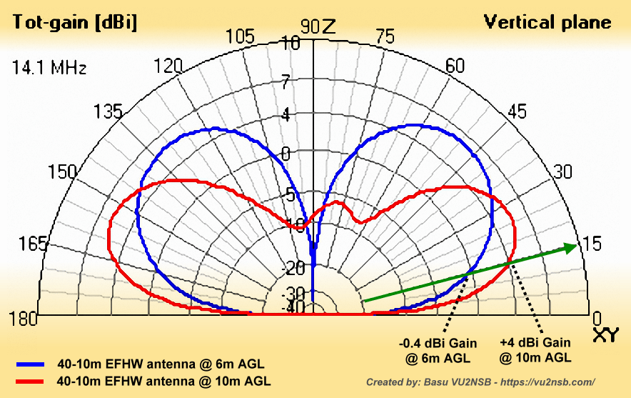
This illustration depicts the effect of raising the height of an antenna further above ground. The results are remarkable. Although the peak lobe gain of the antenna does not change noticeably, the useful gain at low takeoff angles as required for medium and long-range DX communication is substantial. The blue pattern is for an EFHW antenna at 6m AGL, while the red pattern is for the same antenna at 10m AGL. Just by raising it by 4m increases low angle DX gain substantially. For instance, at 15° the gain increases by about 4.5 dB.
It should be safe to assume that by applying best practices and using proper ferrite core based choke Baluns and other means, whereby the CMC on the feeder is attenuated by around 40 dB, it should help in cutting down the receiver noise significantly. Ideally, one should avoid End-fed antennas if possible since they are notorious for EMI/RFI and noise-related issues. Experienced operators would perhaps know how to tame these antennas and make them behave, but a rookie operator might be clueless and end up with a not so happy situation. If possible always use balanced antennas since they are generally very well behaved.
Nevertheless, whatever might be your choice, the golden rule is to never let the transmission line become a part of the antenna by letting it carry unbalanced currents (CMC). If due diligence is applied, a minimum of 2 S-units (if not more) that is equivalent to 6 x 2 = 12 dB (conservative estimate) of noise reduction could be achieved by taming CMC, thus allowing our original SNR shortfall of 20 dB to be now reduced to 20 – 12 = 8 dB.
Another 6 dB Power Advantage
Our example station was operating on FT8 with 25W TX power. On SSB radiotelephony, the TX power would usually be 100W for the same station running barefoot. This is equivalent to another 6 dB enhancement… Therefore, the 20 – 12 = 8 dB SNR shortfall that we had above will now be reduced further to 20 – 12 – 6 = 2 dB only.How do we bridge this 2 dB SNR gap? … A small bit of work on our antenna to optimize its radiation should put us way past the 2 dB shortfall. Let us check it out below…
Tweaking the Antenna Height, Location, and Orientation
If we recall, our example station runs an EFHW antenna at around 4.5-6 m (15-20 ft.) above ground level (AGL). During the Low/moderate SSN conditions, as is prevalent these days, the ionospheric skips for HF propagation occur efficiently at low elevation takeoff angles, typically in the range of 8-15°. Let us assume the easiest condition of 15° radiation takeoff angle… What happens in the case of our EFHW antenna at 6m (20 ft.) AGL on the 20m band? … And, what would happen if we were to make an effort to elevate the antenna wire to a somewhat higher level? … Let’s examine.Take a close look at the elevation section of the EFHW antenna radiation pattern that I have provided in the associated illustration above. There are two pattern curves, one in blue color which represents our EFHW antenna at 6m (20 ft.) AGL. The red color pattern is for the same antenna after elevating it by another 4m (13 ft.), resulting in the new height AGL of 10m (33 ft.). Both these patterns are for the 20m band.
In the above illustration, I have marked the 15° elevation angle intersection points across both patterns. The available gains at 15° elevation under both conditions are also marked. We find that the 15° elevation EFHW antenna gain @ 20 ft. AGL is -0.4 dBi, while the gain after the antenna is raised to 33 ft. AGL is +4 dBi.
As a matter of general interest, it could be worthwhile to note that although at low takeoff angles around 15°, give and take ±10° or so, there is a substantial enhancement of available gain on account of increased antenna height. However, despite the change in antenna height AGL, the maximum published gain of the antenna as specified by at the peak of its major lobe remains nearly constant… A typical rookie mistake is to assume the published maximum antenna gain to be the gospel truth. They often expect it to be the effective gain under all situations… Such a thing practically never happens. The antenna height AGL plays a vital role, especially at low and medium elevation takeoff angles.
Simply, by raising the antenna wire by a modest amount from its original height, we could extract an additional gain of 4.4 dB over the initial gain. Not to mention the fact that when the antenna is raised higher, it will also be slightly further away from various electrical appliances, etc., that might be producing QRM… I am not even considering this additional benefit.
Let us now finally apply the 4.4 dB gain benefit to the calculations that we made so far… The final results of bridging the SNR shortfall will now be 20 – 12 – 6 – 4.4 = -2.4 dB. The negative shortfall means that we now have a situation where there is a surplus above the 0 dB SNR threshold… The effective SNR for SSB radiotelephony operation with our tweaked and improved station has become promising. Instead of the -20 dB situation that we had in the beginning, now our radio station can copy and work SSB voice QSOs too. If one were to apply one’s mind, there would surely be several other possibilities of improvements and tweaks of such simple nature that could optimize the existing amateur radio station setup.
The use of higher TX power with the use of a linear PA is rarely warranted unless someone needs to frequently break into huge pileups. That’s where additional transmitter power could come in handy. In most other circumstances, it doesn’t help at all.
Ultra-Narrow Bandwidth Digital Modes – Aren’t they great for HF amateur radio?
Well! … Maybe they are, or maybe they aren’t.
Okay! … So, what’s wrong with the ultra-narrow bandwidth digital modes? … Perhaps, nothing wrong per se, however, from a practical amateur radio communication perspective, there are quite a few things about them that do not fit into what amateur radio stands for.
A major takeaway from the fundamental tenets of Shannon’s Mathematical Theory of Communication is that the lower is the communication channel bandwidth, the lesser is the quantum of the rate of flow of information. In other words, the narrower the modulation bandwidth, the slower is the rate of communication. Of course, the side benefit is that even a radio station with an overall poor quality setup might still be able to communicate.
The question now is, how far do we stretch this weak-signal narrow-bandwidth game, just to be able to overcome our goof-ups and shortcomings? Some of the narrow-bandwidth digital modes are very good provided we use them to overcome extremely difficult and hostile propagation conditions. However, when we fall back on these modes not because of the hostile and difficult conditions but to compensate for avoidable reasons like our laziness or sheer ignorance that led to a poorly setup radio station, then there surely must be a far bigger problem with regard to our approach and attitude towards amateur radio.
As far as these weak-signal digital modes are concerned, we perhaps need to draw a line based on their operational characteristics. For an amateur radio operator, the priority is to communicate among the peers, and in the process develop a variety of skills related to radio communication which could either be technical or simply procedural in nature. An average radio amateur is not typically involved in regulated, organized, or formally funded research on radio propagation or communication. Of course, some of us with the necessary skill do conduct informal experiments all the time because of our passion, but at the end of the day, we are amateurs and pursue amateur radio as a (meaningful) hobby.
Therefore, why should a large section of our community spend the better part of their time being tied up to various semi-automated weak-signal digital modes that typically exchange information between software running on both ends of the radio communication circuit through computers connected to the transceivers? These software are the actual communicating entities because they decide what limited information they would like to send out. The radio amateur doesn’t have much of a say. So, without getting into legalities, can we truly justify such communication to have been conducted between two radio operators… No!, I don’t think so.
Moreover, what is the nature of these communications? There is practically no information exchanged between human beings on either side of the circuit. There is no conversation or message exchange possible with these modes. One might say at this stage that a few modified versions of these digital modes now allow the operator to type in a short message too… Sure, they do… But at what cost? … It might take 30 seconds to 2 minutes for one short sentence to be transmitted. Is it really what we would expect during regular communication? Is it really worth it?
IMHO, a variety of practical narrow-bandwidth digital modes are available, but when we steer into the realm of ultra-low bandwidth modes, that’s when it no more remains worthy of being used for amateur radio on a regular day-to-day basis. If a text-mode digital modulation system allows free-form text to be keyed in from the keyboard and also features sufficient speed of data throughput that allows it to keep pace with the typing speed of an average typist, then it should be perfectly fine. However, if people have to wait for a minute or so for a short phrase or a sentence to go through, then perhaps that’s not what we need.
What I stated in the paragraphs above may be food for thought for some of us. As amateur radio operators, we must embrace and explore all kinds of development in technology. There is no second opinion on that count… However, should we embrace these technologies for no other reason than the unfortunate fact that we might be hiding from the shortcoming of our radio stations? I agree that there would be circumstances where one might have exhausted all options of further enhancing their station due to unavoidable limitations. In such cases, it should be okay to try out the only viable modes available.
Under normal circumstances, after applying adequate due diligence towards optimizing the amateur radio station setup, if someone were forced to take a call then it is quite understandable. On the other hand, when someone doesn’t even make any worthwhile effort, that’s when it becomes unfortunate…
On the other hand, if someone has a nicely decked ham shack with good fancy (LED, halogen, or fluorescent) fancy lighting with cheap inbuilt electronic ballasts, uses mediocre SMPS to power their rigs, inadequate station groundings, lack of ferrite bead filters where necessary, installing their HF antennas near the ground or building walls or surface of roofs at low heights, carelessly installed unbalanced and unbalanced antennas, not using adequate transmission line (coaxial cable) CMC filtering, etc., etc., and then going on to run ultra-narrow bandwidth modes like FT8/FT4, etc., at full TX power level to establish contacts; then I think that the station operator has a lot of introspection to do… This is because if the above-listed shortcomings are corrected, the radio station would most probably be able to come alive. The stations that were never heard before on CW and SSB radiotelephony will be heard on the bands. A return voice call to people heard calling CQ would certainly receive a response.
Remember, the HF bands are not really dead. It is usually the overall radio station that is dead mostly due to deaf and noisy antenna systems… Of course, the choice of the correct band at the given time plays the most important role in the entire equation… Do the required tweaks to your radio station, familiarize yourself with the variations in propagation conditions at different times and different bands, and then, get down to working SSB telephony with a 100W on a wire antenna… Happy DXing.


(14 votes, Rating: 5.00) - Please vote the article with your valuable star rating. Thanks! Basu (VU2NSB)


SSN SSNf(10.7) – Real-time Solar Data


