

Radio Transceiver S-Meter – Lesser known facts
However, on a brighter note, let us also acknowledge that some of the newer, and modern high-end transceivers that are becoming available these days rely heavily on SDR techniques and often extensively employ DSP to replace various receiver functions that were traditionally done using analog circuits. DSP functions bring to fore several advantages including a far more accurate implementation of S-Meter characteristic response.
In this article we will unravel the mysteries, lies, and truth behind typical S-Meter behavior and also dwell into some of the common confusions that are sometimes created. From the perspective of HF amateur radio operators, the ramifications of comparing a typical but often a grossly miscalibrated radio receiver S-Meter with a reference standard S-Meter is perhaps the biggest bone of contention that often leads to confusion amongst a lot of operators. Many claims and counter-claims are often made by various operators regarding the prevailing noise-floor levels on the HF bands based on what they observe on the S-Meter. These observed magnitudes of perceived noise vary quite extensively from person to person. Needlessly to say, the variations in reportage is expected because each QTH is subjected to (especially in urban locations) different magnitudes of ambient noise (QRM) levels.
However, there is more to these noise floor variations than just the QRM levels associated with a QTH. Everyone seems to overlook another important but not so obvious factor which I propose to unravel here. This factor manifests due to quite significant differences in the S-Meter calibration that we find in different HF radio transceivers. The variations are unspecified and their behavior might be different from manufacturer to manufacturer and even from one model to another.
S-Meter calibration Standards as approved by ITU/IARU
To begin with, let me categorically establish the ground rules so that our measurements and comparisons will conform to international standards as laid down by ITU/IARU… As I mentioned before, some of the latest models of amateur radio transceivers having full SDR system design architecture with 100% DSP implementation have successfully implemented well-calibrated S-Meter sub-systems. However, it is also important to remember that at the time of writing this article, these new breeds of transceivers are quite expensive and are not in widespread use.
Most of the currently popular commercial amateur radio HF rigs, including some of the widely used rigs that were sold over the last decade or two, unfortunately, have very high meter scale error and the manufacturers don’t seem to care. They are only calibrated at S-9 point of the scale with an antenna terminal signal injection of 50 micro-volts. The rest of the S-meter scale completely falls apart from the point of view of calibration. This is the common situation with all popular manufacturers including Icom, Kenwood, Yaesu, etc for almost all models of TXRs being manufactured. These S-Meter issues continue to remain, to varying extents, even in the extremely popular rigs like the FT-991A, the TS-590SG, or the IC-7300, etc… Readers may feel shocked at this disclosure but sadly, it is true.
Before we actually look into the quantum of S-meter errors on commercially manufactured amateur HF transceivers, let us first understand the S-meter standards.
Internationally accepted norms for S-units as approved by IARU are as under..
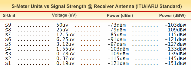
A table of S-Unit calibration standard as adopted by ITU/IARU. The table is a ready reference for corelating S-units to either the RF voltage at antenna terminal or to dBm or dBW power reference.
The corresponding signal power levels in dBm or dBW are self-explanatory. The signal voltage equivalents in micro-volts are from a signal source with 50 ohms impedance fed into antenna input terminals of the TXR having a corresponding load impedance of 50 ohms. In view of the above, we note that S9 is pegged at 50uV level while each S-unit interval is fixed at 6dB.
S-Meter Calibration – Facts & Myths
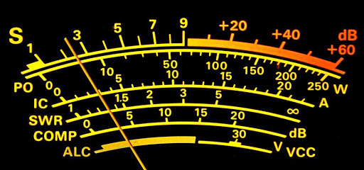
A typical multi-function meter found on a communication radio receiver or a transceiver. The upper-most scale is traditionally always the S-Meter scale. Check out the logarithmic character of the S-Meter scale.
The manufacturers are aware of it but their argument is that practical S-meters are not intended to be absolute value measuring instruments. They are only supposed to be indicators of relative signal levels… Fair enough, I accept their point of view.
Therefore, we as users must also accept this limitation and should not try to use it for any purpose which it is not intended for. For instance, we must not try to correlate band noise-floor levels based on an HF rig S-meter readings and then compare it to the actual prevailing levels that could be measured and validated using professional Test & Measuring Instruments. That would be quite unfair to expect an average amateur radio transceiver to live up to those standards… Other than the lab-quality T&M instruments, fairly precise signal/noise level measurement may also be made using communication receivers. However, these are professional receivers which are quite expensive and do not fall under the amateur radio rig category.
How bad is the S-meter calibration error on typical amateur radio HF rig? I would say it is pretty bad. Further down in this article I will provide benchmark measurement results for several real-world HF transceivers and we will also examine why is it so difficult to provide a better and a more decent S-meter.
Before we proceed further, let us quickly summarize the typical behavior expected out of these real-world S-meters…
- Most S-meters are fairly accurate at the S9 level. This is the level at which they are calibrated in the factory.
- Above S9 and below S9 at progressively greater deviation the error increases.
- Usually the readings are reasonably acceptable between S6 and S9, but most of them tank out below S5 or S6.
- S-meter on most rigs die out below S4 level with only a few which survive down to S3. In either case, even though there is a measurable deflection, the error is horrendous and usually, the actual prevailing S4 would show S1 on the meter.
- In some transceivers, the bottom limit of the S-meter is only down to S5 where it dies out and shows S1.
S-Meter Limitations based on Hardware of Transceivers
The question before us is why is it so? As I mentioned earlier it is a limitation of the methods used to implement S-meter. Without going into a detailed and complex narrative on S-meter designs and behavior of variable gain semiconductor amplifier circuits, I will mention a few pertinent points to avoid making this article incomplete.
1) In most SSB transceivers, the S-meter is derived from the error correction voltage produced by the AGC circuit. The AGC circuit is a formed of several cascaded stages of bias controlled variable gain IF amplifier stages.
2) The AGC circuit is a negative feedback loop used to automatically reduce or increase the collective IF amplifier gain so as to produce a reasonably constant level at its output. The control voltage generated by an analog level comparator is fed back to the IF amplifier to control its gain.
3) The above-cited error control voltage is sampled and processed to produce S-meter deflection. This becomes possible because the strength of the RF input signal into the receiver determines the extent to which the IF AGC gain needs to be reduced or increased. Hence the feedback control voltage is a reflection of the signal strength.
4) So far so good… But we have a practical problem at hand. The control voltage to gain relationship of semiconductor amplifiers is neither linear nor logarithmic nor does it follow any square law or inverse square law. An approximation can be made over a small control segment, but when we need to cover a dynamic range of 50dB or more then we have this problem. Some of the semiconductor devices including both bipolar junction transistor or Field Effect transistors (JFET and MOSFET) often follow an nth order polynomial function. Hence it becomes practically impossible to maintain an S-meter calibration over a wide dynamic range.
5) To compound problems further, most HF rigs do not have enough gain surplus dynamic range. Quite often the AGC opens up the IF amplifier to maximum gain at around S3-S4 (~1uV) level. Therefore there is no further change in correction voltage and hence the S-meter reading on such rigs settle down to S1 even though the actual prevailing level may be S3-S4.
6) Finally, the bias to gain function of transistors is highly temperature dependant and hence the S-meter reading below S5-S6 level (the cramped portion of the semiconductor gain curve) becomes even more inaccurate.
Now the next logical question would be, can anything be done about the above-cited issues? Is it possible to have a good S-meter?
Of course, it is possible. The professional communication equipment does it and so does the Test & Measurement (T&M) industry. We routinely measure levels with accuracy better than 0.5-1 dB. This would translate into 1/10th S-unit… We use techniques like RF front-end digitization or analog computation techniques to implement IF stages having definitive mathematical transfer functions to define gain/control relationships… But that’s another story, perhaps for another day.
S-Meter Behavior Test Results and its Ramifications
Let us put our focus back on the core objective of this article. Let me now present you with test results of S-meter calibration accuracy measurements which I did on several amateur HF transceivers over a period of time. Top-notch and well-calibrated professional T&M instruments were used in an ambient temperature-controlled laboratory environment. Each piece of an instrument used had a valid certificate of calibration not older than 60 days.
Please see the attached graphic table for a summary of S-Meter test results… However, in a nutshell, the basic findings are as under…
1) True to expectations, all rigs were found to be fairly well calibrated at S9 level.
2) Above S9 the accuracy deviated widely with increasing error. Unreadable values are marked as (x).
3) Towards the lower side most rigs held up well till S7 level. Below S7, the error magnitude increased sharply. S6 level was barely acceptable for subjective comparisons but was no good for any quantitative measurements.
4) Signal at S5 rung a death knell for all rigs irrespective of the cost or complexity.
5) S3 or S4 was the graveyard for all tested rigs which displayed the S1 bottom…
6) No signal below S3/S4 could even marginally deflect any of the S-meters. The meters stood dead at S1.
I could not lay hands on an Elecraft-K3. This would be my dream rig. I would love to see how it behaves… I wish I had one of these, it would surely be a dream come true… But, it’s not going to happen unless someone gifts me a K3 with pan adaptor… Wow! Just kidding…
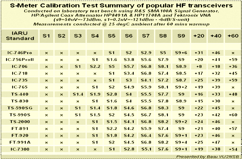
The result of the S-Meter calibration accuracy test performed on randomly sampled popular amateur radio transceivers of various makes and models. Almost all rigs have shown quite an excessive deviation from expected results.
Finally, let us wind up this article by recognizing the limitations of a typical amateur HF rig S-meter... Let us use it as a relative reference of signals we hear on the bands. Let us not treat it as a measuring instrument. Finally, let us not be mesmerized by the low noise-floor levels seen on S-meter especially on top bands, and fool ourselves into believing that the HF band noise is low..
Whatever is stated in this article are not unknown facts... All the HF radio rig manufacturers are aware of these limitations. We, the radio amateurs also need to understand and accept it.


(16 votes, Rating: 5.00) - Please vote the article with your valuable star rating. Thanks! Basu (VU2NSB)


Ham Rig Reviews Coming Soon
SSN SSNf(10.7) – Real-time Solar Data


