Introduction to Antenna fundamentals
most types of antennas that we encounter in the real world are typically some kind of a standing-wave antenna. They are usually dipoles or some derivative or combination of a set of dipoles. One might ask at this stage that what about complex antennas like a Yagi or a Cubical Quad or a Log-periodic Array (LPDA) or a Parabolic dish antenna? Are they too dipoles? The answer is, yes, they are.
It may appear counter-intuitive and confusing at first but we will gradually explain the concepts in relevant articles under the Antenna section of our website. However, we must also bear in mind that there are a few types of antennas that are not essentially dipoles. for instance, a magnetic-loop antenna or several types of traveling-wave antennas, etc. Since these antennas are less commonly used, we will cover them separately under the sub-section on Miscellaneous Antennas.
The performance of any antenna, especially for an HF ground station, is typically influenced by several factors which include its basic design, structural material used to build the antenna, the placement of the antenna with respect to the surrounding environment, the topography of the terrain, proximity to the ground, the ground quality which includes the soil dielectric constant and conductivity, antenna orientation (vertical, horizontal, oblique, etc.) with respect to ground, etc. Many of these factors are also equally applicable to terrestrial VHF/UHF communication antennas.
All antennas have some important key attributes which we will try to examine briefly over here. These major attributes including several others will be covered under various dedicated articles on the subjects.
Antenna Gain and Directivity
Antenna gain is not an absolute quantity. It is an attribute that is measured relative to another reference antenna. It signifies the relative enhancement in the performance of the antenna in comparison to the standard reference antenna, both while transmitting (TX) and receiving (RX). The gain of a transmitting antenna is characterized by its Power gain, whereas, the receiving antenna gain is termed as Directivity gain. However, one must remember that the power gain of a TX antenna does not imply that the total power fed to the antenna by the transmitter would increase or get multiplied in any way while transmitting.
Since the power output from the transmitter does not get enhanced due to the antenna gain, then the logical question would be, what does the antenna power gain really mean? To answer this, we must take a quick look at our reference antenna w.r.t which the gain is measured. since the good old days, a resonant half-wave dipole in free-space (called the Standard Dipole) was taken as the reference. The gain attributes of all other antennas were measured in relation to this standard dipole and such gains are designated as dBd where the last character (d) designates a dipole reference. The standard reference dipole has a shortcoming that although its characteristics can be replicated in free-space, its radiation pattern is shaped like a donut and is not uniform in all directions in a 3-dimensional (3D) space.
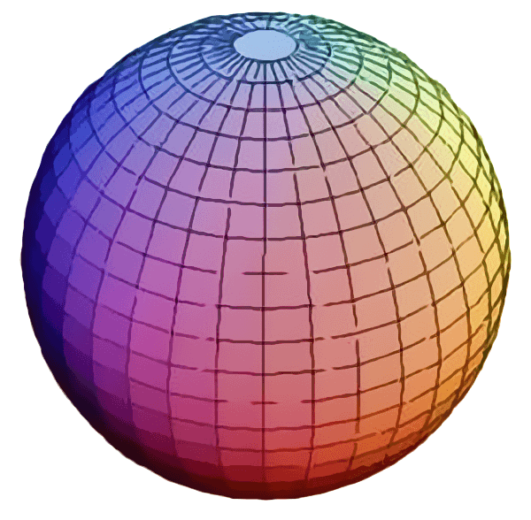
Therefore, another reference antenna was conceived for the purpose. This is the Isotropic Antenna. The Isotropic antenna is an imaginary antenna that does not exist in the real world. However, the upside is, that this antenna is characterized by a perfectly spherical radiation pattern and hence deemed to have a uniform radiated power density in all directions in the 3-D space. The Isotropic antenna can readily be adapted as a reliable reference for the purpose of mathematical modeling which is extensively used for contemporary antenna designs. Antenna gain measured with reference to the Isotropic is designated as dBi where (i) stands for isotropic. The Isotropic antenna has now more-or-less become the de-facto reference antenna amongst the industry and the community of antenna designers. For the sake of portability and compatibility between the older standard dipole and the Isotropic antenna as a reference, the gain relationship has been mapped between the two.
The Standard reference dipole has been set to have a 2.15 dB gain over the Isotropic antenna. Hence, the gain specified in dBd can be converted to dBi by simply adding 2.15 dB to it. Similarly, a dBi to dBd conversion can be made by subtraction.
After having defined the reference antenna, let us now examine the gain attribute of an antenna. In case of our reference Isotropic antenna, since the radiation pattern is a uniform 3D sphere, let us use the analogy (though not perfect) of an air-filled spherical balloon. Let the air in the balloon represent transmitted energy (power) and let us assume the surface of the balloon to be representative of the gain.
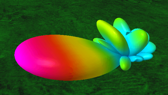
Let us focus on the antenna fundamentals and try to figure out why do most practical, real-world antennas have a finite positive gain over an isotropic antenna? If we examine their radiation lobe patterns, we notice that they invariably have shapes that restrict radiation in certain preferred directions. None of them have a perfect spherical pattern. Has this something to do with gain? Absolutely… That’s precisely what results in antenna gain. The more they limit their energy radiation to narrow and restricted lobe patterns, the greater is the gain.
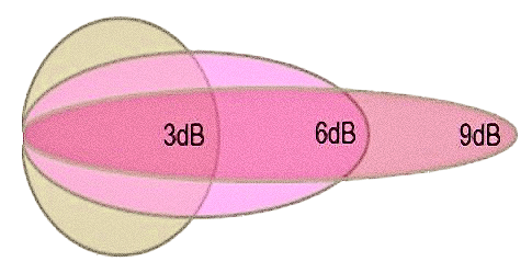
So, what really happens? Let us take the dipole for instance and try to reshape the spherical balloon that we created for the Isotropic antenna. Let us take the balloon and squeeze it in the middle from two opposite sides. As a result, we will find that the balloon would expand in the other directions as the air inside would push against the elastic surface of the balloon. The more you squeeze, the more will be the stretching out on the other sides. This expansion of the surface is representative of the gain. Even though we have not changed the quantity of air in the balloon (transmitter power), the far tip of stretched balloon surface will expand to a greater distance away from the center in comparison to the radius of the isotropic sphere.
Instead of squeezing t the middle, you can squeeze it and reshape the balloon in any way you want (assuming the balloon in our analogy does not burst), thereby, even turning the original spherical shape into a thin oblong shape. The length of this oblong shape will be far greater than the radius of the sphere, thus representing high gain which would now be similar to perhaps a Yagi antenna pattern.
To summarize the notion of antenna power gain, we found that by concentrating transmitted power in narrow beams in one or more directions and preventing the energy from being distributed in other unwanted directions, the antenna successfully manages to project a spatially controlled radiated power thus effectively increasing the power density in the desired direction without requiring the transmitter to furnish additional power. similarly, while receiving, the intercepted EM wave is cumulatively added to produce higher induced voltage and current on the antenna. The TX and RX behavior of an antenna is by-and-large reciprocal. However, in a separate article, we will discuss more details of antenna directivity gain for RX.
Antenna Efficiency
The efficiency of an antenna is an important attribute. It determines how much power from a transmitter that is transferred to it via the antenna feed point actually gets transformed into radiated EM energy. In a practical real-world antenna, there could be several factors that contribute to loss and consequent power dissipation. most amateur radio operators who run high power (QRO) would know that quite often their antennas would become warm. Those living in places with a very cold climate have often noticed that the snow that might have deposited on the antenna wires and elements often start melting when they transmit for long lengths at a time as in a ragchew session. Broadcast station engineers know that the soil in the vicinity of the antenna farm becomes warm. Large megawatt power stations also heat up the foliage near the TX antenna and often destroy the vegetation in the immediate vicinity. All these reflect on the overall efficiency of the antenna system.
Losses on a typical antenna are caused due to many factors. Materials used for the fabrication of the antenna are the primary loss contributors. The wires, pipes, tubings, etc which form the radiating structure have a finite resistance which contributes to the loss. Moreover, at radio frequency (RF), the current does not flow through the entire cross-section of the conductor. The RF current gets pushed to the outer surface of the conductor and flows only through a very small depth from the surface. This is called Skin effect. The higher the frequency, the smaller is the skin depth. Therefore, the effective cross-section of the antenna elements gets effectively reduced by several orders of magnitude in comparison to the physical cross-section. This further compounds resistive losses.
Another factor that may add to the losses in some types of antennas is the dielectric loss in various types of insulators. Usually, low dielectric loss insulators like ceramic are used to minimize such losses. Many amateur wire antennas use wires like PVC insulated wires as antenna elements. Other than altering the resonant length of the antenna, such insulations also add their small share of dielectric dissipation loss. Many multi-band amateur radio antennas use LC traps or Coax traps to achieve multi-band capability. These traps are notorious for being quite lossy. Even the finest and well-designed traps sport unwanted losses, but sadly most of these built by amateurs have a poor unloaded Q factor and consequently a pretty horrendous amount of loss.
As we mentioned earlier, the losses due to proximity to the ground (earth surface) are also a variable that adds to antenna inefficiency. The quantum of this loss depends on the quality of the soil in terms of its conductivity and its dielectric constant. This could vary from region to region. fertile and moist soil has low loss, whereas, urban soils and sandy dry desert soil produce a higher loss. Water bodies have low loss, especially seawater. There could be additional losses on account of the location of the antenna installation. Buildings, metal structures, pipes, overhead wires, etc not only cause antenna radiation pattern distortions but also considerably reduce antenna gain due to losses caused by energy absorption.
All said and done, keeping in mind all the above factors while fabricating and installing an antenna would go a long way in maintaining a reasonable antenna efficiency. Please remember, the reason why many operators find it difficult to work enough stations (especially on HF) is not always so much to do with anything else but a poorly planned antenna installation.
Antenna Beamwidth
Taking it forward from our discussion on antenna gain, we find that most regular-sized antennas feature a higher magnitude of gain in comparison to theoretical Isotropic radiators. This is achieved by concentrating radiating energy along with the desired directions by forming radiation lobes. Hence, we need to have a way of quantitatively defining important attributes of radiation patterns of a practical real-world antenna. One of these important attributes is the Beamwidth of the primary lobe.
Although, an antenna may produce several lobes, some of which could be intended by design while some minor lobes may be produced as a side-effect of the beam formation process. The primary (major) lobe is usually the one that stands out from the rest. Different types of antenna designs and structures usually have unique radiation patterns associated with them. An antenna in free space with an unhindered path for energy to propagate in all directions may feature patterns ranging from donut shapes to a pair of diametrically opposite bidirectional lobes or may have the pattern tailored in a way where there is a single major lobe in the preferred direction. In free space, the patterns are normally symmetrical around the axis or plane of the antenna. A notable exception is an asymmetrically stacked antenna array which we will cover in another article. The radiation lobes often look like elongated ellipsoids, like the shape of a typical air-dropped bomb or a torpedo.
The published gain of an antenna is characterized as the peak gain of its major lobe along the major (central) axis of the lobe. To be able to define the effective region of access around the major axis of the lobe the antenna beamwidth is defined. This is the angle formed between the axis of peak gain and an angle where the gain reduces by either 3 dB or 6 dB. Usually, the -3dB angle is specified because it represents the angle at which the power density of radiation falls off to half that of the peak value.
In the case of HF antennas for terrestrial communication, -6 dB angle may be designated since it represents a typical 1 S-unit roll-off at the far-end RX station. Whatever may be the case, the antenna beamwidth parameter provides an insight into the far-end area coverage of the antenna without any significant deterioration in performance. Moreover, it also specifies the degree of acceptable directional misalignment of antennas in a practical point-to-point communication scenario. The total beamwidth is actually equal to twice the -3 dB (or -6 dB) angle measured on one side and is specified as ±(xx)° where XX is the angle on one side.
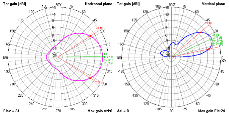
However, the antenna which is located relatively close (in terms of wavelength λ) to a large reflecting surface like the ground in case of a typical terrestrial communication HF antenna, we usually characterize the antenna beamwidth with two different entities. One of them is the Elevation beamwifth while the other is the Azimuth beamwidth. This becomes essential because, on account of the presence of the reflecting ground beneath the antenna, the radiation lobes get altered in shape and are no more completely symmetrical around the peak gain axis. The effect of the ground proximity is usually to compress the lobe pattern across the elevation plane. Hence, elevation beamwidth becomes different from that of the azimuth beamwidth. The positive side-effect of the presence of the reflecting ground surface is to considerably increase the effective gain of the antenna in comparison to the same antenna in free space.
Antenna Bandwidth
The bandwidth of an antenna is another important attribute. All antennas work effectively within a band of frequencies around its nominal design frequency. Beyond the bandwidth-limited frequency span, the performance of an antenna gets severely impaired and makes its use unsustainable. Some types of antenna sport a relatively broad usable band span with some of them covering several octaves. These are known as broadband antennas. The more notable broad bandwidth antennas are the Log-periodic Dipole Array (LPDA), the Discone, the Double Discone, Traveling-wave antennas like the Rhombic, Beverage, etc. However, most of the popular and well-known antennas are resonant standing-wave antennas that have rather limited bandwidth.
Whatever be the type of antenna, its bandwidth is characterized by its ability to maximally and efficiently transfer to itself the power which is delivered to it by the transmitter. The maximum power transfer to a load from a source occurs only when the source and the load impedance match. In a practical scenario, a small amount of impedance mismatch may be tolerated but a gross mismatch may not only be unacceptably inefficient but can have a catastrophic effect on the entire radio station.
The quantum of impedance mismatch between the source and the load is specified by a parameter called the Voltage Standing Wave Ratio (VSWR) which is also simply called SWR. The SWR is equal to the ratio of the load and source impedances and expressed as a ratio like 1:1 or 1.5:1 or whatever. Although some radio transmitters and transmission-line systems are less tolerant, most modern amateur radio equipment can safely handle SWR up to 2:1. However, higher prevalent SWR can be handled with the use of an Antenna Matching/tuning Unit often called the ATU. An ATU does not actually address the SWR problem per se, but only masks its adverse effects and creates an illusion that makes the transmitter believe that all is well.
The use of an ATU to suppress the ill effects of high SWR is not advisable, especially when using Coaxial cable transmission lines because it may severely impair the overall performance of the overall antenna system. Yet, many amateur radio operators use ATU indiscriminately. We will discuss these issues thoroughly in our articles related to radio transmission-lines.
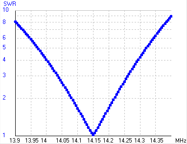
For now, let us assume that a maximum SWR of 2:1 is the acceptable upper limit. At its typical design center frequency, the SWR of a well-designed and well-fabricated antenna is very close to the optimal value of 1:1. As we tune away from this frequency in either direction of the frequency scale, the feed point impedance of the antenna begins to change in both magnitude and phase while the source impedance remains constant. As a consequence, the SWR at the antenna feed-point begins to rise.
At a point, as we alter the TX frequency, the SWR reaches 2:1 and continues to climb further. The frequencies on either side of the center frequency of the antenna where the SWR reaches 2:1 is considered as the maximum recommended boundary limits till which the antenna is expected to perform as per specifications. The frequency span between the 2:1 SWR limits on either end is termed as the antenna bandwidth. Many of the popular HF antennas are limited by the SWR bandwidth and are often incapable of covering the entire available frequency span of a designated amateur radio HF band. Therefore, we so often hear about amateur operators choosing a band segment of focal interest and tuning their antennas accordingly while grudgingly being forced to compromise on the antenna performance across the rest of the band.
Antenna Polarization
Polarization of an antenna refers to the polarization of the EM waves radiated from the antenna. Proper antenna polarization plays a vital role in the Surface-wave (often loosely called Groundwave) propagation of LF, MF, and HF signals. It is also a very significant factor in VHF/UHF and microwave communication. However, in the case of Ionospheric Skywave HF communication, the antenna polarization is inconsequential from the perspective of propagation.
Nevertheless, it certainly plays a noticeable role in picking up man-made environmental noise (QRM) which is quite high in urban and industrial locations. Due to the better surface-wave propagation capability of vertically polarized signals over a longer distance in comparison to horizontally polarized signals, the bulk of the aggregate QRM is vertically polarized. Therefore, a vertically polarized antenna is more prone to pick up a greater magnitude of environmental QRM than a horizontally polarized antenna.
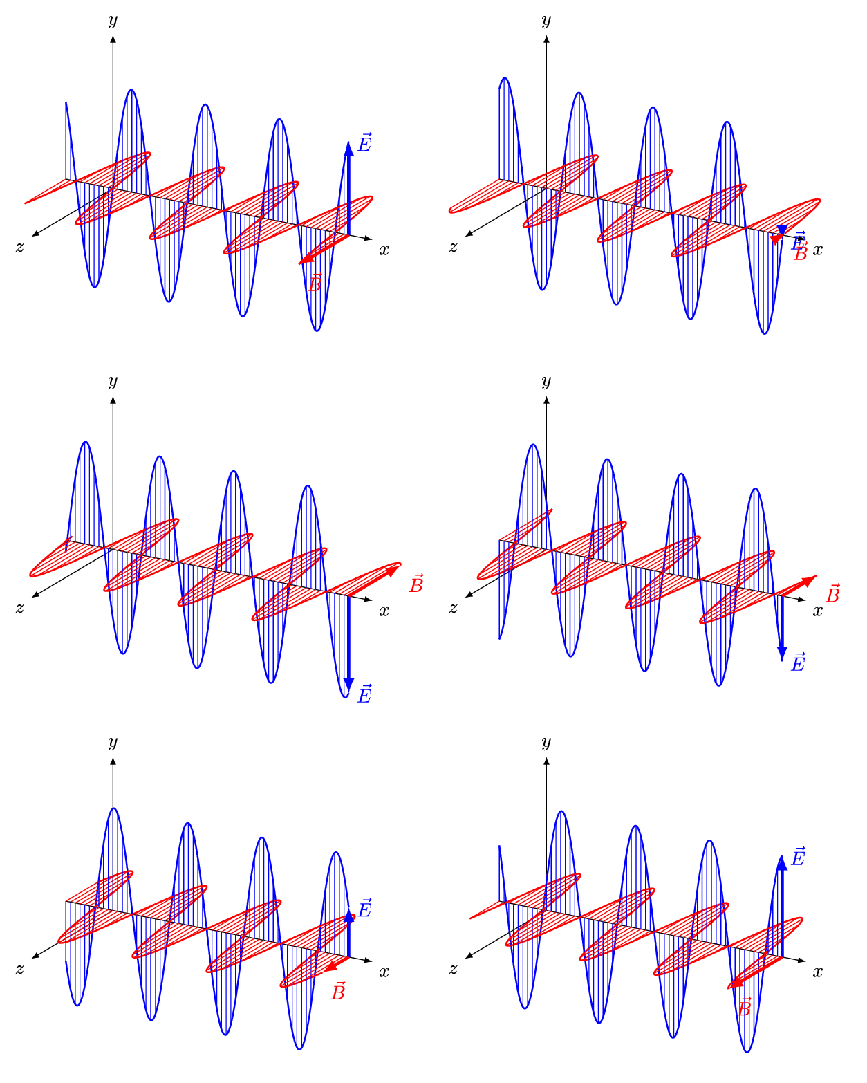
Let us quickly try to understand a bit more about EM wave polarization and how antennas are categorized based on polarization. EM waves comprise of two coexisting components. They are the electric field and the magnetic field. Both these fields exist together, repetitively transferring signal energy between each other as they propagate through the medium at the velocity of light. The electric field and the magnetic field are spatially at the right-angle (orthogonal) to one another. now, if an antenna generates an EM wave so that the electric field component of the EM wave is vertical while the magnetic field is horizontal, then the EM wave and consequently the antenna producing it is called vertically polarized.
Similarly, if the produced EM wave has its electric field oriented in a horizontal plane while the magnetic field lines in the vertical plane, then the wave polarization along with the antenna producing it is also termed as horizontally polarized. In other words, the plane of orientation of the electric field of the EM wave is used as a reference to classify the polarization of the antenna. Typically, the plane of orientation of an antenna element defines the plane of orientation of the electric field of the EM wave. Consequently, antennas like the dipole, other horizontal wire antennas, the horizontally deployed Yagi, etc are horizontally polarized antennas. similarly, a vertical monopole antenna or a vertically oriented Yagi are vertically polarized. Other antennas like the Cubical Quad or a Delta-loop are full wavelength closed loop antennas, hence their polarization is determined by the location of feed point on such antennas.
Barring the earlier cited scenario of ionospheric sky-wave communication, we have stated that antenna polarization plays a vital role in radio communication. The reason is that the receiving antenna receives a maximum signal if the polarization of the signal it encounters and its own polarization is the same. In case the signal polarization is orthogonal (90° rotated) with respect to its own polarization, then the polarization loss at the RX antenna is colossal. Theoretically, no signal would be received, however, since practical polarization mismatch may never be a mathematically perfect 90°, the loss won’t be infinite but yet very high in the order of -20 to -30 dB. This may still mean that the transmission may not be readable at the RX end. This means that both the TX and the RX antennas must have the same polarization for reliable and effective communication in most cases other than ionospheric skip skywave propagation.
There is another scenario that is often applicable to space satellite communication. Many satellites especially the smaller Low Earth Orbit (LEO) satellites are often not fully stabilized on their axis in the orbital plane. They do not use gyroscopic platforms nor are they spin-stabilized. They freely roll, pitch and tumble as they move through their orbit. Therefore, the antennas on these satellites cannot maintain a constant physical orientation vis-a-vis the earth. As they roll and tumble, their antenna orientation and consequently their polarization constantly keeps changing. for an earth station to maintain communication with such satellites, it is neither possible to use a horizontally nor a vertically polarized antenna at the earth station.
Moreover, as the radio waves pass through the ionosphere during both the uplink as well as downlink, it is subjected to a phenomenon called Faraday rotation which causes the polarization of the signal passing through the ionosphere to change. The amount of polarization rotation is unpredictable and depends on the thickness and the density of the ionospheric layers prevailing at that time. Faraday rotation is most prominent at VHF and to a lesser degree on UHF. However, at microwave frequencies, this effect is practically non-existent. The solution to reliably access LEO satellites is to use another type of antenna known as Circularly polarized antennas. Axial mode Helical antennas and Crossed-Yagi are typical examples of circularly polarized antenna… but that’s another story for another day.
Take-off Angle & Radiation Lobes
The radiation take-off angle is another vital attribute that is typically relevant to terrestrial communication antennas. Although this attribute plays a role in the case of VHF/UHF antennas too, due to the short wavelengths involved most antenna installations usually meet the requirements for good low angle radiation even without a proactive effort to ensure it. However, HF antenna installations being relatively much closer to the ground in terms of wavelength may often suffer from inadequate low-angle radiation lobes. Therefore, HF antenna designers, fabricators, and installers need to take adequate care if they wish to achieve low take-off angle capabilities.
Let us examine as to why low take-off angle radiation lobe patterns are often vital for long-range (DX) communication on HF bands using ionospheric skip propagation. The ionospheric layers are located at a height of several hundred kilometers above the surface of the Earth. The earth is nearly spherical in shape and the ionospheric canopy is like a concentric hollow sphere around the earth. Simple geometry tells us that the angle of radiation from an antenna with respect to the surface of the earth would determine the distance at which the EM radio beam would strike the ionosphere.
At high angles, the point of intercept of the radio beam by the ionospheric canopy will be at a shorter distance away from the transmitter, while a low angle beam will travel a longer distance away from the TX station before it encounters the ionosphere. After striking the ionosphere the beam is reflected (refracted, to be precise) back toward earth at nearly an angle equal to the angle of incidence of the beam at the ionosphere. The reflection point at the ionosphere is akin to the apex of a geometric triangle.
Therefore, it is clear that the lower the take-off angle of radiation from the antenna, the greater will be the distance the radio signal will travel in a single skip (hop). Even when multiple skips are required to cover even longer distances, the total number of skips needed to cover the DX distance is the least when the take-off angle is low. Fewer cascaded skips to cover the distance between two DX stations translate into lower signal path loss thus allowing a stronger, more reliable, and more robust communication between the DX stations.
In a nutshell, for relatively short distance ionospheric skip to occur one would need an antenna with only moderate take-off angle capability but for good DX working especially under weak signal conditions, it is imperative to deploy antennas with good low take-off angle capabilities. The take-off angle of an antenna is primarily determined by its height above the surface of the ground. Barring some antenna types like the vertical 1/4λ antenna or its derivatives with an integral ground plane radial system, most of the HF antennas are prone to the effects of ground proximity for determining their take-off angles. As a rule of thumb, the higher the antenna above the ground surface, the better is the prospect of attaining a lower take-off angle.
Feedpoint Impedance & SWR
We noted earlier in this article that the maximum power transfer from the transmitter and feeder system occurs when the feed point impedance of the antenna is equal to the source impedance at the antenna end of the feeder cable. Typically, at radio frequencies, the source impedance is equal to the characteristic impedance of the cable (Transmission line). Another important criterion for maximum power transfer is that the load (antenna feed point) impedance must be as resistive as possible with no or minimal reactive components.
This is because only a resistive load can absorb the power, whereas, a reactive load does not absorb power. That is why we always aim to create an antenna structure that is resonant at the desired frequency of operation. Resonance implies totally canceling out all capacitive and inductive reactive components and leaving only the resistive load component to present itself to the source.
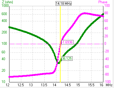
An interesting but an often misunderstood fact about antenna resonance is that the feed point impedance of an antenna at its resonant frequency may not necessarily mean the lowest possible VSWR (SWR). While attempting to tune the antenna for lowest SWR we often end up detuning the antenna off-resonance. for instance, let us take the example of a 1/4λ monopole antenna. The feed point impedance of a typical resonant monopole is 36Ω.
A typical transmitter with 50Ω source impedance connected to a 52/54Ω coaxial cable will present no better than a nominal 54Ω source impedance to the antenna. Therefore, the SWR at the resonant monopole feed point will be the ratio of 52:36 or 1.44:1 but nothing less. Any attempt to reduce the SWR further by adjusting the antenna element will actually result in detuning the antenna off-resonance. The reactive components of the antenna impedance will show up in addition to its resistive component leading to a detuning point where the complex impedance (Z) may become equal to the source impedance and hence show a 1:1 SWR on the meter.
The feed-point impedance of a practical antenna, if it is matched to the source, will certainly transfer maximum power to the antenna but does it always mean that your antenna system is very efficient? .. Not necessarily… Although the best power transfer takes place, how much of it is actually radiated is a million-dollar question? There are many antennas available in the market which might have a feed point impedance that matches nominal source impedance, yet they radiate poorly.
This brings us to the concept of Radiation resistance. Other than reactances that can be tuned out by resonating the antenna, every antenna has primarily two types of resistive components. They are the Radiation resistance and the Loss resistance which are both in series. A poorly designed antenna with 50Ω feed point impedance may have only a small radiation resistance (say 20Ω) while the loss resistance may be (say 30Ω). Hence, the total is 50Ω and it will be a perfect match to the coaxial cable transmission line source and show a perfect 1:1 SWR on any meter.
However, this antenna will radiate only about 30% of the applied power on account of radiation resistance, while the balance 70% will be lost as heat due to the loss resistance. Hence, an efficient and well-designed antenna will always keep the loss resistance to a minimum in comparison to the radiation resistance, even if it means that the total feed point impedance would not allow a direct impedance match.
List of Articles under this Section
Principles of Radiation How does antenna radiation occur? The basic question before us is how does an antenna work? Why does antenna radiation occur? Why does a wire carrying RF current radiates to produce EM waves which travel through free space or the...


