

Is it Ground Wave or surface Wave propagation?
In this article, we will examine various modes comprising of the Ground wave with special emphasis on the Surface Wave which is quite unique and special with a propagation method that is so different from the others. The properties of the surface waves make them very useful for establishing robust, reliable and fade-free communication within its coverage area. Though the surface wave coverage range is rather limited and is also a function of the operating frequency, it is one of the predominant modes used for broadcast coverage by MF radio broadcast stations around the world. The surface wave propagation mode is also exploited for short and medium-range communication by amateur radio operators on the lower frequency HF bands (top bands).
In our narrative below, I will begin by explaining Ground wave propagation followed up by a deeper explanation of its various components including the surface Wave phenomenon. We will also expand upon the not so often talked about phenomenon of First Fresnel Zone Clearance which is actually rather vital for providing clarity to the essential working concepts of Line-of-Sight (LOS) propagation. LOS is used daily by thousands of amateur radio operators to carry out VHF/UHF radio contacts without even giving it a second thought. It is taken for granted. Rarely does anyone stop to think how or why the contact became possible, or, more importantly, why a contact could not be established even though common sense suggested that it should have worked… Let us now figure out the hows and whys of Ground wave communication.
What is Ground Wave Propagation?
In this section, we will examine Ground wave propagation which has unique properties and finds an important place especially on the lower frequency HF bands like 160m, 80m, 60m, and 40m ham radio bands. However, let us take a holistic view of the principles of the ground wave propagation scenario before we return our focus to MF and HF ground wave propagation methods.
Ground wave comprises three distinctively different components. They are…
- Direct wave (Space wave)
- Ground Reflected Wave
- The Surface wave.
At MF and HF radio bands for terrestrial communication, it is the Surface wave that is predominant while the Space wave and Ground Reflected wave play a negligible role.
Although the Direct wave and the Ground Reflected wave are not significant at lower frequencies, they play a vital role in terrestrial VHF, UHF, and Microwave propagation. On these bands, they are primarily responsible for what we call Line-of-Sight (LOS) propagation.
Direct and Reflected Wave Line of Sight (LOS) Communication
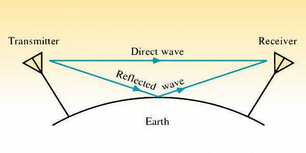
Direct and Ground reflected waves in Ground wave propagation.
Let us assume that the signals reach the receiver through both the direct and ground reflected paths and are combined together at the RX antenna. If both the signals combine in phase, they reinforce the signal strength at RX, but if they are not in phase they destructively combine to reduce the signal strength at RX. Hence, though the VHF/UHF signal progressively becomes weaker as the TX to RX distance increases, we find that it is not strictly a smooth reduction.
As the RX station location is moved further away, the signal strength reduction follows a bumpy or roller-coaster type downhill progression. This is because, with the change in distance, the phase difference of the direct and the reflected wave varies continuously and hence the net signal strength after vector combination also varies in accordance.
Moreover, due to the curvature of the earth, LOS propagation is usable up to the distance limited by the horizon. The horizon distance is also determined by the height of the TX and RX antennas above ground. The greater the height of antennas, the longer is the distance to the horizon. Having said that, we must also recognize that the distance of the radio frequency horizon is usually far greater than the typical optical horizon. Let us take a quick look at the radio horizon below.
The Radio Horizon
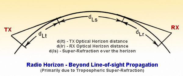
Beyond the LOS communication over the Radio Horizon.
The light (wave) that we can see travels in a straight line irrespective of the atmospheric medium, provided the density of the medium is homogenous, however, the radio waves have a tendency to slightly bend towards the surface of the earth along its curvature as it travels along. On account of this, radio waves can arrive from a TX station that lies at a location beyond the distance that we can see. The extended horizon applicable to radio waves is called the Radio Horizon.
This extended radio horizon effect is produced due to an atmospheric phenomenon. The lowest region of the atmosphere is called the Troposphere which starts from the surface of the earth and extends to 14-18 Km above the earth’s surface. The temperature of the air reduces as we move higher and also the density of the air reduces at higher altitudes. This alters the Refractive index of the air as the height above ground increases. Due to these differences in the Refractive Index, the radio wave starts bending.
The air at greater height has a lower refractive index and hence the propagating radio wave experiences a very marginal increase in velocity as it reaches higher altitudes. This causes the top portion of the EM wave-front (passing through at oblique angles) to travel a little faster than the lower portion, thus resulting in the earthward bending of the radio wave.
How much longer is a typical radio horizon?
To compute the Radio Horizon distance, let us first find the optical horizon based on the height of the observer above ground, and thereafter we will factor in the element of simple atmospheric refraction constant as a modifier.
Let us assume the following…
d = the horizon distance in Km.
h = the observer or antenna height in meters.
Based on the curvature of the earth, the optical horizon distance is calculated by the following equation.
d = 3.57 x √(h)
Let us now introduce a numerical constant which is based on the typical refractive index gradient of the lower atmosphere. By applying the constant K to the above equation we can derive the radio horizon distance asunder.
d = 3.57 x √(Kh)
The above equation gives us the distance to the radio horizon from one antenna. However, in a radio communication scenario, we have two radio stations, the TX and the RX stations, one on each side of the radio horizon. If the antenna heights of the two station antennas are denoted by h1 and h2, then the maximum possible distance for LOS communication between the two radio stations over the radio horizon can be found by the following equation.
d = 3.57 x (√(Kh1) + √(Kh2))
the Constant (K) is related to the refractive index of the atmospheric medium
At this point in our narrative, let me state that the above-computed distances are based on K=4/3. This constant is applicable under normal conditions of atmospheric refraction. However, there are quite often conditions when the atmospheric refractive index gradient is different, and hence the magnitude of K changes.
![Super refraction]() At times, we might experience sub-normal refraction resulting in a lower magnitude of K and consequently a shorter radio horizon distance. However, more interestingly, we quite often experience elevated values of K that results in what we call the atmospheric super-refraction.
At times, we might experience sub-normal refraction resulting in a lower magnitude of K and consequently a shorter radio horizon distance. However, more interestingly, we quite often experience elevated values of K that results in what we call the atmospheric super-refraction.
If we have an extremely high elevation of the K value resulting in a steep refractive index gradient near the surface of the earth, then a propagation duct is created between the lower part (within about 1Km altitude) of the atmosphere and the earth’s surface. This atmospheric surface duct phenomenon is also called atmospheric Trapping. Under this condition, the VHF/UHF radio waves can propagate around the curvature of the earth across quite long distances. At times, Super-refraction and Trapping may occur after incessant rainfall.
Though super-refraction may occur anywhere over a landmass, it is more frequent near coastal areas. As the colder air from a region blows over a layer of warmer air at the surface, it enhances the vertical profile of the refractive index gradient. This results in an increase in the value of K. If we were to apply a larger value K constant to the equation above, we find that the radio horizon distance is now much more than what we computed for normal refraction conditions.
Atmospheric super-refraction conditions can often allow VHF or UHF radio contacts to be established across a couple of hundred kilometers. VHF/UHF amateur radio DX operators often leverage these conditions to work exciting DX.
Hence, if we summarize, we find that maximum LOS propagation distance as shown above under various conditions of atmospheric refractive index gradients determines the limit of LOS propagation coverage over the surface of the earth. We also notice that the higher the TX antenna or the RX antenna or both, above the surface of the earth, the greater will be the maximum possible terrestrial LOS propagation coverage distance.
To compute the Radio Horizon distance, let us first find the optical horizon based on the height of the observer above ground, and thereafter we will factor in the element of simple atmospheric refraction constant as a modifier.
Let us assume the following…
d = the horizon distance in Km.
h = the observer or antenna height in meters.
Based on the curvature of the earth, the optical horizon distance is calculated by the following equation.
d = 3.57 x √(h)
Let us now introduce a numerical constant
d = 3.57 x √(Kh)
The above equation gives us the distance to the radio horizon from one antenna. However, in a radio communication scenario, we have two radio stations, the TX and the RX stations, one on each side of the radio horizon. If the antenna heights of the two station antennas are denoted by h1 and h2, then the maximum possible distance for LOS communication between the two radio stations over the radio horizon can be found by the following equation.
d = 3.57 x (√(Kh1) + √(Kh2))
the Constant (K) is related to the refractive index of the atmospheric medium
At this point in our narrative, let me state that the above-computed distances are based on K=4/3. This constant is applicable under normal conditions of atmospheric refraction. However, there are quite often conditions when the atmospheric refractive index gradient is different, and hence the magnitude of K changes.
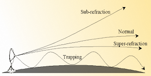
Propagation ray behavior under different atmospheric refraction conditions.
If we have an extremely high elevation of the K value resulting in a steep refractive index gradient near the surface of the earth, then a propagation duct is created between the lower part (within about 1Km altitude) of the atmosphere and the earth’s surface. This atmospheric surface duct phenomenon is also called atmospheric Trapping. Under this condition, the VHF/UHF radio waves can propagate around the curvature of the earth across quite long distances. At times, Super-refraction and Trapping may occur after incessant rainfall.
Though super-refraction may occur anywhere over a landmass, it is more frequent near coastal areas. As the colder air from a region blows over a layer of warmer air at the surface, it enhances the vertical profile of the refractive index gradient. This results in an increase in the value of K. If we were to apply a larger value K constant to the equation above, we find that the radio horizon distance is now much more than what we computed for normal refraction conditions.
Atmospheric super-refraction conditions can often allow VHF or UHF radio contacts to be established across a couple of hundred kilometers. VHF/UHF amateur radio DX operators often leverage these conditions to work exciting DX.
Hence, if we summarize, we find that maximum LOS propagation distance as shown above under various conditions of atmospheric refractive index gradients determines the limit of LOS propagation coverage over the surface of the earth. We also notice that the higher the TX antenna or the RX antenna or both, above the surface of the earth, the greater will be the maximum possible terrestrial LOS propagation coverage distance.
Antenna Height for Effective LOS
We have seen so far that the LOS propagation mode is essentially a terrestrial propagation mode for short-distance communication with a range limited by the effect of Radio Horizon. LOS mode is technically different from the Free Space propagation mode. Free space propagation is an unhindered mode that is not influenced by the presence of any behavior-modifying object like the earth, atmospheric refraction, etc. For more on Free space propagation, read the article VHF/UHF & Free Space Propagation.
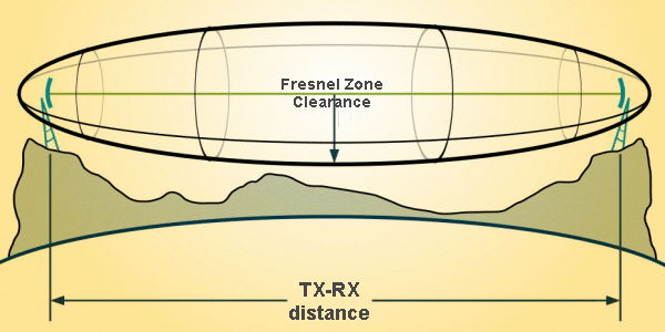
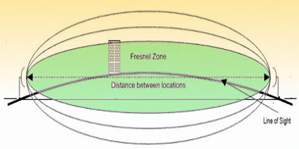
A typical Fresnel Zone between two transmitting and receiving stations.
This is on account of what we call the First Fresnel Zone which needs to be cleared. In other words, the First Fresnel Zone must not have any obstructing, reflecting, or refracting object within the region. For practical antenna heights at HF frequencies, this condition is totally violated due to the proximity of the earth’s surface. LOS propagation is typically not possible on the HF bands. Due to relatively much lower frequencies (larger λ), the height of HF antennas, in terms of wavelength (λ) is always too small to be able to achieve a first Fresnel Zone clearance above the earth’s surface. However, at VHF/UHF and beyond, where λ is much smaller, a practical and feasible antenna can be deployed at heights that qualify the minimum acceptable Fresnel Zone clearance requirement. Since the necessary condition can be fulfilled, the LOS mode manifests as a practical propagation mode.
Without dwelling deep into scientific analysis, let us try to intuitively understand the concept of the Fresnel Zone. Most amateur radio literature often oversimplifies the point-to-point radio communication to be in the form of a straight ray between the points. However, the fact of the matter is that though the wave-front travels in a straight line between points, the eventual aggregate of the signals arriving at the receiver via multiple paths on account of reflection from nearby objects may destructively add up to attenuate received signal strength. The reflection of radio waves from objects in the nearby region around the straight line that is shaped in the form of a 3D ellipsoid creates issues. It is in the shape of a barrel that has a fat belly with the maximum bulge at a distance halfway between the TX and RX points. Please see the illustrations to understand the concept. This is called the Fresnel Zone.
Although the Fresnel Zone comprises multiple concentric ellipsoids, we are at present only interested in the first inner ellipsoid which is referred to as the First Fresnel Zone. This ellipsoidal zone between the two antennas (First Fresnel Zone) must be clear and unobstructed for the LOS propagation to manifest itself with minimum path loss. If any obstructing physical object is present within the Fresnel Zone space in the propagation path, it results in creating an impediment.
How do we find the Fresnel Zone region dimensions?
An illustration depincting First Fresnel Zone clearance failure between two radio stations.
R = 0.5 x √(d x λ)
Where…
R = First Fresnel Zone clearance radius in meters.
d = The distance between TX and RX in meters.
λ = Wavelength of the radio wave in meters.
Perhaps now we are equipped to use the above equation and our intuition to draw an important inference. The fact is, that the greater the wavelength, the greater will be the required Fresnel Zone clearance radius.
Therefore, on HF bands, the required heights of the antennas to fulfill this requirement is impractically high. The surface of the earth itself acts as an object that behaves as an obstruction within the first Fresnel zone. Most HF antenna installations miserably fail to achieve the required clearance due to a deep breach of the first Fresnel zone by the surface of the earth. Hence LOS attenuation is so very high that the direct wave LOS mode is not workable.
However, at VHF/UHF and higher frequencies, the wavelength is much shorter and hence the required clearance radius is smaller, LOS mode becomes practical. Although even at VHF/UHF, under general service usage, full Fresnel Zone clearance is seldom achieved, LOS is still feasible due to only a fractional breach of the clearance zone. This introduces additional signal attenuation beyond the theoretical LOS values, but the communication is still possible. Greater the breach of the first Fresnel zone clearance region by the presence of obstructing objects like the curved earth surface below, buildings, trees, etc, the greater is the signal attenuation. Ideally, up to 80% clearance is considered nearly ideal, while a clearance down to 60% is usually considered the worst-case acceptable limit.
Ideal LOS conditions are usually fulfilled in professional installations for terrestrial microwave communication. Many of us must have seen those very tall terrestrial microwave relay towers with two Parabolic Dish antennas at the top facing in opposite directions. They form a part of an ideally set up cross-country microwave terrestrial link designed for optimum performance, minimum loss, and efficient LOS communication with full Fresnel Zone clearance.
Surface Wave Propagation
The Surface wave propagation method has special relevance in MF and HF communication in the 300 kHz – 30 MHz frequency band. When the height of the transmitter antenna operating at these frequencies is small in comparison with its wavelength (λ), Surface wave propagation becomes feasible and predominant. In the MF and lower frequencies of the HF band, this propagation method can be used to reach distances up to several hundreds of Kilometers.
Surface wave propagation is probably the most robust and reliable mode of terrestrial communication. Surface wave propagation is not influenced by geophysical or geomagnetic disturbances, seasons, and solar or galactic activities. It is the only terrestrial radio propagation mode that is empirically proven to be nuclear survivable for reliable communication through distances well beyond the radio horizon.
The most important property of the Surface wave is that it propagates parallel to the ground. The signal attenuation or propagation path loss will depend strongly on the terrain constants (conductivity and permittivity), as well as other factors like polarization, antenna height, distance, and frequency. The use of vertical polarization is best suited for viable Surface wave propagation. This is because the ground rapidly attenuates the signal by absorbing and dissipating the horizontally polarized EM wave.
However, it is also true that even a vertically polarized surface wave propagation can suffer quite a high attenuation over poor quality grounds like deserts, etc. The poor quality ground would drastically reduce coverage distances. On the other hand, circuit paths over the moist land, lake, sea or water bodies, etc minimize losses because of the higher terrain conductivity.
The principle of Surface wave propagation makes it quite unique. It appears to travel by clinging to the surface of the terrain and travel long distances along the curvature of the earth. The heights of antennas used for surface wave propagation are fairly low, yet the signal travels hundreds of kilometers and way beyond the radio horizon. This becomes possible because a portion of the Surface wave wave-front penetrates into the surface of the terrain while it travels. It’s like wading through a shallow pond with knee-deep water. Try to briskly walk through the water and you will discover a tendency to lean forward when you try to do so.
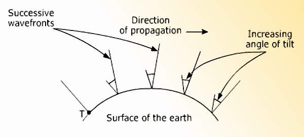
A representative illustration of the Surface wave progression by progressive bending of wave-front.
The larger the wavelength, the greater is the penetration depth for a particular kind of soil characteristic. This penetration depth is also referred to as the Skin Depth. This phenomenon results in a slight forward bending of the wave-front as it propagates. The wave-front forward tilt ensures that it follows the curvature of the earth while propagating rather than moving away from the earth’s surface at a tangent and traveling out into the sky.
The propagating surface wave is also affected by the properties of the terrain into which it penetrates while progressing. Terrain properties play up in two ways.
The first thing to note is that if the terrain conductivity is poor then it results in greater penetration depth, hence causing the cumulative increase in the angle of tilt of the radio wave to become quite large. This will eventually result in a situation when the wave-front which was initially launched perpendicular to the earth would undergo excessive forward tilt that increases progressively. After a while, having traveled some distance, the wavefront tilts enough to become horizontal and collapse into the terrain. This results in the termination of the surface wave.
Hence, as we discussed above, poor soil conductivity which accounts for greater terrain penetration and excessive tilt is not good for long-range surface wave propagation. Dessert terrain and dry soil have poor conductivity, whereas moist or fertile soil, water bodies, lakes, and oceans have very good conductivity resulting in lower penetration depth and lower angle of wave-front tilt. This ensures a fairly long surface wave propagation range. Optimum soil properties will lead to just the correct amount of wavefront tilt in consonance with the curvature of the earth to result in very long-distance surface wave coverage.
Let me also mention at this juncture that after rains when the soil is soaked wet, the surface wave propagation range often alters due to the temporary change in soil conductivity.
The second factor is the rate of surface wave attenuation or reduction in field strength with an increase in distance. This is directly linked to the electrical conductivity of the terrain. Poor terrain conductivity of dry soil results in higher losses. As the propagation distance increases more energy from the electric field of the EM wave is lost by the wave-front which is dissipated in the terrain and manifests itself as heating of the soil. If the electrical conductivity of the terrain is good as in the case of moist soil or water bodies, the energy dissipation in the terrain is much less. This ensures adequate signal strength at much longer distances.
The third factor that determines the surface wave propagation range is the frequency of the transmitted signal. Since each cycle of the EM wave undergoes a certain degree of wave-front tilt and attenuation due to energy loss on account of soil heating, the more the number of EM wave cycles for a particular distance, the higher is the surface wave propagation loss. Intuitively this translates to the fact the surface wave coverage distance will be shorter at higher frequencies (shorter wavelength) as compared to lower frequency (longer wavelength) bands. This is because the number of EM wave cycles required to cover a distance at a lower frequency (longer wavelength) will be fewer in comparison to the greater number of wave cycles at a higher frequency.
The fourth vital factor is the polarization of the Surface wave-front. Vertically polarized radio waves are best suited for surface wave propagation, whereas the horizontally polarized signal attenuates very rapidly with distance and is no good for any meaningful surface wave propagation. In a vertically polarized radio wave, the electric E-field of the EM wave is perpendicular to the surface of the terrain, while in the case of a horizontally polarized wave the E-field is parallel to the terrain surface and skims over it. In a vertically polarized wave, the vertical E-field and its return path are partially embedded in the terrain due to surface penetration, whereas in case of horizontal polarization the entire return path of the E-filed lies under the terrain resulting in high power dissipation on every EM wave cycle. Hence the attenuation loss for vertical polarization is much less than horizontal polarization.
Other factors like terrain irregularities, surface clutter in urban areas due to buildings or structures and the type of terrain vegetation do not play a significant role in determining propagation prospects at MF and lower HF frequency bands.
Lut us summarize the surface wave propagation properties as…
- Reliable terrestrial propagation at MF and HF over several hundred kilometers.
- The propagation range reduces with an increase in frequency.
- Vertical polarization ensures longer range compared to Horizontal polarization.
- Moist terrain and water bodies result in longer range compared to dry soil.
- Stable signal strengths at the RX site, not affected by geophysical conditions.
- The inverse-square law of free space propagation principles does not apply.
MF Radio Communication and HF Ground wave
We stated at the beginning of this section that Ground wave consists of three components, the Direct (space) wave, the ground reflected wave and the surface wave. However, at MF and HF under normal practical conditions, the Ground wave only comprises of the surface wave component. The effect of direct wave and ground reflected wave is non-existent. This is because at the MF/HF frequencies most practical antennas are erected at a short height above the ground in terms of wavelength.
For instance, a 40m band antenna set up at 30m (100 ft) height is only at 0.75λ above ground. The minimum antenna height requirement for viable direct wave propagation is determined by plotting the Fresnel Zone between the TX and RX antennas. It is important that the elliptical-shaped First Fresnel Zone is unobstructed. However, due to the close proximity of the earth’s surface, this principle is grossly violated and therefore direct wave propagation is not feasible. This is the major difference observed between the properties of Free Space (direct wave) and Terrestrial LOS propagation that set them apart.
If we cut out the technical jargon and look at the whole thing from another perspective, we could simplify it by saying that due to the low antenna heights (in terms of wavelength) and the close proximity to the earth, the two rays, the Direct Ray and the Ground Reflected Ray both have almost identical path lengths. Furthermore, due to the extreme shallow gazing angle at which the Ground Reflected Ray hit the earth’s surface, its reflection coefficient is -1. This means that the reflected ray is 180 degrees out of phase with the direct ray. However, due to practically equal path lengths, they add up destructively at the RX antenna and cancel out.
Our take away from this discussion is that under normal MF and HF terrestrial ground wave propagation scenario, the Space Wave component does not exist and the only mode available is Surface Wave propagation.
That’s all for now but we will present many in-depth articles that would further expand up all the concepts that we introduced here. We will do it by building up block by block so as to keep our discourse as intuitive as possible and yet unravel the mysteries.
List of Articles under this Section
- HF Radio Surface Wave propagation (Ground Wave) Surface Wave propagation and coverage on the HF radio bands is well known to radio amateurs. Especially, on the Lower frequency HF bands called the Top Bands which includes the...


(21 votes, Rating: 5.00) - Please vote the article with your valuable star rating. Thanks! Basu (VU2NSB)


Ham Rig Reviews Coming Soon
SSN SSNf(10.7) – Real-time Solar Data


