

Getting started on ISS Cross band Repeater
However, the above activities in the past required adherence to ISS activity schedules. Radio amateurs could make radio contacts with the astronauts but only when they were free to operate amateur band radios… The new Cross Band Repeater that has now been installed on the ISS is an absolute game-changer. Now, there is a fundamental difference. The ISS Cross Band Repeater allows two geographically separated operators on the ground to establish contact with one another. The ISS is only the facilitator just like any other communication satellite. One doesn’t need to wait for the astronaut to be available for contact. Moreover, with this repeater, it is no more an earth station to space station contact but between two earth stations.
What makes the ISS Cross Band Repeater so unique and special?
Many people with experience in amateur radio satellite communication might say that we already have a variety of satellites with either linear transponders or FM repeaters. We even have a Geostationary satellite transponder (QO-100) at our disposal So, what’s the big deal? Fair enough… I agree that amateur radio satellites have been in operation since the 1960s and we always had great fun using them. Yet, this new ISS Cross Band Repeater is certainly worthy of special attention, especially, from the perspective of hundreds of thousands of new amateur radio licensees from around the world, who initially might have limited experience and limited equipment at their disposal.
The induction of the ISS Cross Band Repeater tears down the barrier of the yesteryears that might have been keeping amateur radio satellite communication beyond the reach of an average amateur.
Let us see what this repeater system onboard the ISS has to offer…
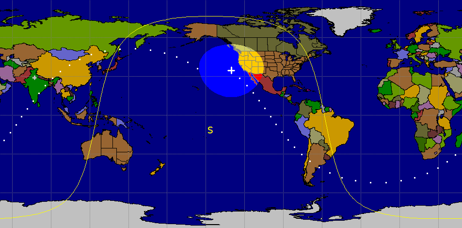
Typical impression of the sub-satellite footprint of the coverage at a specific time. In this illustration, the ISS is moving on a descending pass near the west coast of USA. The highlighted region depicts the region of ISS signal coverage.
The ISS has 3 antennas for VHF/UHF operation on the amateur radio band. They are 1/4λ antennas with optimized performance characteristics.
The uplink receiver front-end of the ISS Cross Band Repeater system is very sensitive and has low noise characteristics that provide approximately -123 dBm (12 dB SINAD) sensitivity. Therefore, the ISS repeater can respond to relatively weak signals that might be produced from low power amateur radio rigs like the Hand-held (HT) radios outputting merely a couple of watts into a regular whip antenna. Theoretically, it may even be possible to establish an ISS Cross Band Repeater contact with as low as 1W from a dual-band (2m/70cm) HT and a whip antenna. Although 1W might be cutting it too fine. However, one can comfortably work through the ISS repeater with 5W 2m HT uplink power.
Though it works with an HT whip antenna on most of the medium and high elevation passes, it would certainly be nice to have a set of 2m/70cm outdoor omnidirectional antennas like either the Turnstile, the QHA, Lindenblad, or the Eggbeater installed in the clear on a rooftop. This way a horizon-to-horizon strong and robust contacts on every pass is guaranteed.
Another important factor that makes contacts via the ISS Cross Band Repeater possible with very moderate equipment is the fact that the orbital altitude of the ISS is quite low. It is approximately 420 Km above the earth’s surface. As a result of this, the link distance between the earth station and the satellite during its pass becomes less. Compared to a higher altitude satellite, the Line-of-sight (LOS) distance to the ISS is relatively smaller. On, high elevation angle passes, the ISS is often visible with the naked eyes as it fleets across the sky.
However, there is a downside to the lower orbital altitude of the ISS too… The foot-print radius circle of communication coverage distance on the earth is lower because of the lower orbital altitude, In other words, the distance between two earth stations that might simultaneously fall within the coverage area of the passing satellite gets reduced in comparison to what one might expect from another satellite at a higher altitude.
Despite the lower orbital altitude of the ISS, the coverage circle on the ground at any point during its overhead pass is usually about 2200 Km in radius (4400 Km diameter)… However, it is not possible to work across this entire range. Limitations are caused by various factors, like near horizon obstructions, additional ground clutter noise, ionospheric and tropospheric signal bending and distortion, etc…
Therefore, it is safe to assume that the fringe areas near the outer periphery of the foot-print circle are not reliably accessible. Normally, it would be safer to consider the coverage range radius to be around 85-90% of the theoretical radius. This should be nearly equivalent to the orbital pass elevation of greater than approximately 10-15°. Satellite at elevations below 10° over the horizon is usually difficult to work unless you have a dedicated antenna setup with the required characteristics.
This brings us to another important point related to the antennas needed to work through the ISS, or any other LEO satellite in general. As I mentioned earlier, one can indeed work through the ISS repeater using a 2m/70cm FM HT along with a regular whip antenna. However, working from horizon-to-horizon would not be possible with such a setup. The radiation pattern of a typical whip antenna mounted on an HT will have pretty poor low takeoff angle performance. Most of the energy will be radiated at higher angles. Moreover, the problem is further compounded by the fact that the distance between the earth’s location and the satellite (Slant Range) is maximum when the satellite is near the horizon which gradually becomes less as the satellite climbs higher above the horizon.
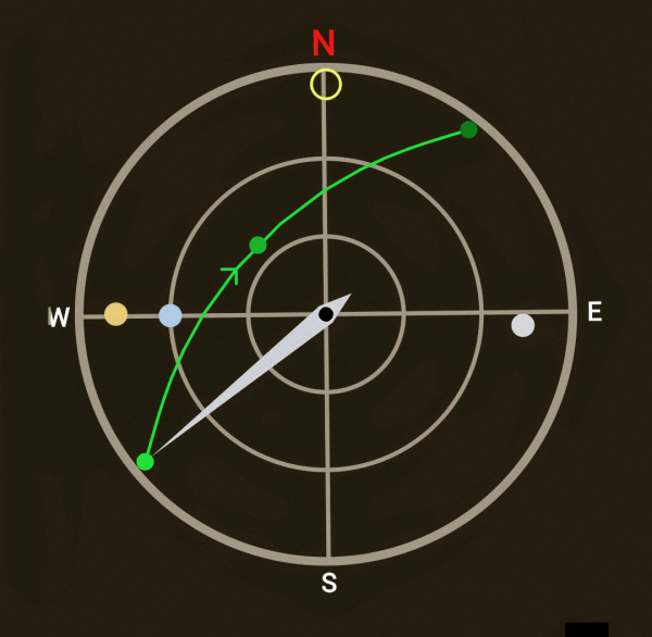
This is the polar map of the sky as the satellite (ISS) ascends from the horizon on one side, gradually scoots across the sky to eventually descend below the horizon on the other side. The outer circle depict maximum range at zero degree elevation angle. The subsequent inner circles represent 30° and 60° respectively. The center of the circle represents 90° elevation. All passes are not overhead passes and hence do not pass through the center…
The above-cited requirement is a tall order for a typical HT based operation. Therefore it is almost impossible to acquire the ISS with an HT and a whip antenna at low elevation angles. Typically, one could expect viable HT based operation when the ISS pass is at an elevation greater than 25-30°. At lower elevation angles, HT based ISS communication would most likely fail.
One might now say, fair enough! I will work the ISS when it climbs above 25-30° during a pass and would ignore it when it is at lower angles near the horizon. I would still be able to maintain contact with the ISS over a large angle range. If I miss out on the initial (near horizon) 30 ° on either side, wouldn’t I still be able to work across 180 – (2×30) = 120° arc across the sky? … Sure! you would, provided you have an overhead pass… Ah! good enough. That’s what one might conclude. However, the fact of the matter is that it’s not as simple as this.
If you dig into the spherical geometry of concentric circles, to your dismay you would discover that the total time spent by an orbiting satellite below 22° elevation on either end of the pass is approximately 70% of its pass period. Only the balance 30% of the passage time is at elevation angles above 22°. Moreover, this is only applicable in the case of direct overhead passes. In the case of all other lower elevation passes, the fraction of time spent by the satellite above 22° elevation is far lower than 30%.
In our HT case scenario of working the ISS, we might not even acquire the bird at 22°. It might typically be 30° and above. Therefore, the acquisition period of the ISS pass using an HT would perhaps only be about 20% or less of its passage time.
Now, what does all this mean? Let’s see…
The orbital altitude of the ISS is 420 Km. This translates to a sub-satellite footprint circle on earth that would have a diameter of only 4000 Km. As the ISS would hurl across the sky footprint circle that denotes satellite access will glide across the map. The time between the ISS appearance above the horizon until it disappears below the horizon on the other side would be maximum for an overhead pass. This is proportionate to the diameter of the footprint circle. In the case of the ISS, the maximum horizon-to-horizon pass duration is approximately 12 minutes.
Apply the above to the HT with a whip antenna scenario. We would be able to access the ISS (above 30° elevation) for about 20% of its passage time. This translates to 12×0.2 = 2.4 minutes… This doesn’t appear to be a rosy picture. Does it? No, it doesn’t… Therefore the bottom line is, although the ISS Cross band Repeater can be accessed using a whip antenna mounted on a regular dual-band HT, it would only occur for a very brief duration and only during the high elevation angle ISS passes.
To comfortably, conduct QSO via the ISS Cross band Repeater, it would be vital to be able to acquire and maintain access to the repeater for as much of the entire duration of the ISS pass. A low elevation angle acquisition of the ISS is important. For this, one does not need a higher power base-station VHF/UHF rig. The power output of even a typical HT at 5W is adequate. What one needs is a better antenna with enhanced low radiation takeoff angle capabilities. It doesn’t mean the one might need an Az/El steerable antenna like multi-element Yagis or Helixes. That would be an overkill for working the ISS. All that one might need is a good omnidirectional satellite antenna. It would be nice if it were to be circularly polarized, as it would result in reduced fading. I have cited a few of these antennas earlier in this post. You could also check out various articles on satellite antennas on this website.
A simple antenna enhancement as cited above is all that you might need to work the ISS over almost its entire 12-minute pass as against only a small faction, a little over 2 minutes that would be possible with the whip antenna. Moreover, the whip antenna would only acquire the ISS on high elevation passes and would let you establish contacts over smaller distances (typically 1000-2000 Km). On the other hand, a proper antenna with a near horizon-to-horizon access capability will let you work the ISS on practically every local pass (irrespective of the pass elevation). Moreover, due to your ability to acquire the ISS near the horizon, you might be able to work better DX up to 3000-4000 Km.
ISS Cross Band Repeater – Radio & Orbital specifications
The repeater equipment used on ISS is a customized Kenwood TM-D710GA VHF/UHF FM radio transceiver. This is an excellent piece of equipment and the customization has been done on the menu and control software, the output power has been capped to a maximum of 25W (though it runs 5W as of now), and more importantly, the cooling system has been converted to continuous operating forced air cooling arrangement. This is necessary because, in space where the gravity is practically zero, the regular convection air cooling does not work since the warmer air can no more go up while the denser and heavier colder air would also not descend… No gravity to do it.
The antennas used for communication on the amateur radio bands consist of VHF/UHF monopole antennas. There are three such antennas on the ISS and are used for various purposes. However, all said and done, they are all linearly polarized antennas with nearly omnidirectional radiation patterns. The effective antenna gains are nominal and close to 0 dB or perhaps a little more.
I am leaving you with the orbital specification of the ISS (Zarya) right below for the benefit of those who might be interested. Unlike most LEO communication satellites, that operate in high inclination polar orbits, the ISS orbital inclination is much less at 51.644°. The prime focus of the ISS is generally the inhabited parts of the globe.
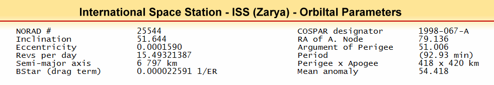
These are the Orbital specifications of the International Space Station (ISS). It broadly defines the general orbital dynamics of the satellite.
We will do a few quick calculations below to derive the minimum system requirement of the radio equipment needed by an amateur radio operator to be able to work via the ISS repeater. Although I will keep the mathematics to the bare minimum, any reader who might feel intimidated by this part of the narrative may skip over to the next section without losing much of the context.
The radius of the earth is 6371 Km and the ISS flies overhead at an orbital altitude of around 420 Km above the surface.
As a consequence, the nearest point for the ISS to the observer on the ground is when it is directly overhead. This minimum distance is 420 Km.
How much would be the maximum possible distance when the ISS is very close to the horizon either when it is just beginning to pop up in the acquisition phase (AOS - Acquisition of Satellite) or about to sink below the horizon (LOS - Loss of Satellite) at the end of the pass. During either of these near horizon conditions, the distance is largest. This distance is also equal to the satellite foot-print radius...
The foot-print radius can be approximately calculated as,
R(fp) = √(2 x H x Er)
where...
R(fp) - is the foot-print coverage circle radius of satellite on earth.
H - is the orbital altitude of the satellite which is 420 Km for ISS.
Er - is the earth's radius which is equal to 6371 Km.
Please note that the above equation is a simplified approximation of the far more elaborate trigonometric solution, which I deliberately avoided to keep things simple.
After solving the above equation for the ISS, we find that R(fp) = 2313 Km. After adjusting this figure to account for near horizon fringe area, we find that the realistic foot-print radius would be approximately 1900-2000 Km.
Hence, the maximum earth station to ISS distance could be 2000 Km, while the minimum distance is 420 Km. Now, let us calculate as to what link budget is required to work across both these extreme boundary value distances...
The earth station to satellite communication is essentially always free-space direct wave communication and hence is governed by Friis Transmission Equation given below. Please refer to my article on VHF/UHF & Free Space propagation for more detail.
Loss(dB) = 20log(D) + 20log(F) + 32.4 - GR - GT
Minimum Distance Overhead ISS Scenario (420 Km)
The Uplink on 145.990 MHz @ 420 Km distance (assuming both TX and RX antennas to be isotropic - GR = GT = 0 dBi), on application of the above equation will result in the following...Loss(dB) = 128.15 ~= 128 dB.
The ISS 2m band (TM-D710GA) receiver sensitivity is -123 dBm for 12 dB SINAD.
Therefore, the radio communication link budget shortfall for fulfilling the minimum requirement is 128 - 123 = 5 dBm. This shortfall assumes a TX power level of 0 dBm. The shortfall may be overcome in several ways. Either we could be having antennas on either or both sides of the radio link to collectively make up for 5 dB deficiency, or we could simply increasing the TX power to +5 dBm which would translate to 3.162 mW.
However, there is more to it than the simplistic calculations that we did above. Let us now start taking into account some of the important real-world factors and then see where we stand.
Let us figure out how the signals would pan out when we use an HT with a whip antenna mounted on it. Firstly, we need to compensate for the relatively compromised performance of a typical HT rig mounted whip antenna. Instead of the 0 dBi antenna gain that we presumed earlier, the realistic gain of a radial-less whip on an HT would be more likely be around -5 to -6 dBi.
The other important factor would be the polarization mismatch between the antennas at both ends (ISS and Ground Station). This will wary randomly with the orientation of the whip antenna of the HT and more prominently due to the effects of Faraday Rotation of the signal as it passes through the ionosphere. The average polarization mismatch would be one-half of the maximum possible mismatch (90°), which turns out to be 45°. At 45° polarization mismatch, the theoretical signal attenuation is -3 dB.
There would be other cumulative miscellaneous losses as well as safety margins to be accounted for. Therefore, it would be prudent to assume another 3 dB loss.
Let us add all these additional losses (Antenna Gain + Polarization mismatch + Misc.) together. This would mount to 6 + 3 + 3 = 12 dB.
Now, we would apply this additional attenuation to the 2m uplink link budget shortfall that we computed earlier.
We had 128 - 123 = 5 dB shortfall if our earth station was putting out 0 dBm signal power.
Let us apply the additional loss of another 12 dB as we just calculated to the 5 dB. This brings us to a net link budget shortfall of about 5 + 12 = 17 dB. To overcome this shortfall, our HT (or any rig) must output at least 17 dBm FM RF power on the 2m uplink.
Oh! but is it bad? ... Nah! This 17 dBm is quite trivial... It translates to 50 mW (0.05W). Does this mean that we could trigger the ISS repeater with only 50 mW of TX power? Yes, that's exactly what it means, however, it is only possible when the ISS is directly overhead at 90° elevation where the slant range to the ISS is minimum at 420 Km.
For practical scenarios where the ISS may be at various elevation angles as it passes through the sky, the slant range is far higher, and therefore we need far more TX power output from our rigs than 50 mW.
In the chart below, let us see what might happen under different conditions and what we might need to do. We must also remember, so far we have dealt with a 2m uplink scenario. The 70cm downlink from the satellite requires more TX power from the ISS repeater. This is because as per the Friis Transmission Equation that we examined earlier, the free-space propagation path loss increases with the square of the frequency. Hence, (437.800/145.990)2 = 9.42 ~= 9 dB. Most amateur radio HT rigs under the ground station operating conditions would rarely have an effective sensitivity any better than -119 to -121 dBm for 12 dB SINAD under typical quiet environment operating conditions. Therefore, it would be safe to assume another 3 dB downlink shortfall on this account. The total additional downlink budget shortfall would be an additional 70cm link loss of 9 dB + 3 dB receiver sensitivity loss. This amounts to 9 + 3 = 12. Therefore, on top of the 12 dB losses for the 2m uplink (Ant. Gain, Polarization, Misc.), we have another 12 dB loss on the 70cm downlink thus making the total additional downlink loss as 24 dB.
Based on our discussion so far, let us examine what it means... The chart below shows the uplink and the downlink signal budgets for ISS Cross band Repeater based communication using an HT with a regular HT mounted whip antenna. The chart shows the calculated results for what to expect when the ISS passes over at various elevation angle, consequently resulting in different slant range distances.
We can clearly see below that it is not possible to maintain access to the ISS all the time using a portable HT setup. We can only access and work through the ISS across a smaller range circle region on the sub-satellite footprint area. The access below an elevation of 25-30° is not feasible. Therefore the range distance is also restricted to 1000 Km or less in comparison to the available 2000 Km typical footprint radius. It also means that approximately 70% of the total pass time of the ISS, it will not be accessible. Only on the balance 30% time, during a close approach to the highest elevation pass point, it will be possible to work using the HT.
Also note that the uplink on 2m band is never really the bottleneck. You will be able to trigger the ISS repeater easily even when it is near the horizon with a typical HT that puts out 2-5W. The problem will be the downlink. With the whip antenna of your HT, the reception of ISS signals on the 70cm band gets restricted to shorter slant range and high elevation ISS positions only... Of course, if they choose someday to run the ISS repeater downlink on 25W (instead of 5W as of now), which the equipment is capable of, then there will be no problem. We will be able to access the ISS repeater from horizon-to-horizon using the HT with a whip antenna. Check out the link budget table below and you may discover that the shortfall on the downlink when the satellite is at the horizon is around 43 dB. At present, the 70cm ISS Tx is at 5W or 37 dBm. If they TX at 25W, then it would be 47 dBm. This would overcome the 43 dB shortfall by a comfortable margin of +4 dB to spare.
Therefore, please do not attempt to increase TX power, as it will not serve any purpose. If you want to work over the full pass, get yourself a better outdoor antenna with characteristics suitable for satellite work. Do not fall into the trap of opting for high gain vertical collinear omnidirectional antennas as many have done only to discover that it won't work. The vertical collinear produces low angle radiation patterns that are great for terrestrial communication but are pretty miserable for satellite work.
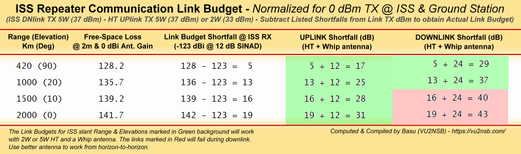
This chart depicts the feasibility of accessing the ISS Cross band Repeater using a typical dual-band 2m/70cm HT with a self mounted whip antenna. The chart provides several details of uplink and downlink signal attenuation conditions with the satellite positioned at various elevations and slant ranges... Read the article for more details.
Important tips on working through ISS Cross Band Repeater
In this article, I have tried to explain various important factors related to operating via the ISS 2m/70cm Crossband Repeater. Hereunder, I will list out a few vital points that one should keep in mind.
- ISS features a V/U repeater. This means that the uplink frequency is VHF and is 145.990 MHz at the time of writing this post. The downlink frequency is UHF and is 437.800 MHz.
- The nominal setting for the TX frequency on your transceiver would be 145.990 MHz and the RX frequency would hence be 437.800 MHz.
- Orbiting satellites including the ISS produces Doppler frequency shifts due to the continuously varying relative distance between the satellite and the observer on earth. The onus of accounting for and correcting Doppler shifts lie with us, the earth station operator. The satellite cares a damn whether we can work through it or not. Hence, it does not lend a helping hand in making any corrections for us.
As the ISS rises above the horizon and till the time it reaches its maximum elevation, the following happens...
- Downlink Doppler Shift - The downlink frequency from the ISS transmitter at 437.800 MHz would appear to be higher than that. Therefore, we will have to tune our TXR to receive at the Doppler-shifted higher frequency. The magnitude of the Doppler shift and consequently the receive frequency will not stay constant. The RX frequency Doppler shift will be maximum when the ISS is near the horizon. As the ISS gradually climbs in elevation, the magnitude of the Doppler shift gradually starts dropping, till the shift becomes zero at the maximum elevation of the ISS pass (like when it is overhead).
The maximum Doppler shift of the ISS downlink frequency is when it is near the horizon is almost 9 KHz for the 70cm downlink frequency, while this shift is 0 KHz at the highest elevation. Therefore, as the ISS appears near the horizon the starting RX frequency of our TXR could be set approximately 9 KHz higher (437.809 MHz). As the ISS climbs higher in the sky, the amateur radio operator would need to reduce this RX frequency gradually till it is brought down to the zero shift frequency of 437.800 MHz.
After reaching the maximum elevation point during its orbital pass, the ISS begins to recede till it reaches the horizon and finally sinks below it. The Doppler shift behavior will be opposite during this receding phase as compared to the above-described approach phase.
While the satellite is receding, its distance to the earth station starts increasing resulting in an opposite Doppler shift. The RX frequency (downlink) would now gradually begin to reduce below the 437.800 MHz that we had at maximum ISS elevation. This Doppler shift will eventually increase to approximately -9 KHz near the receding horizon. - Uplink Doppler Shift - Doppler shift also applies to the uplink frequency of our earth station transmitter. The behavior is similar to what I described above for the downlink. The frequency of our transmission as received by the ISS receiver would appear to be higher during the satellite approach phase, become zero at the maximum satellite elevation point, and then gradually shift to a lower frequency as the ISS reaches the horizon during the recede phase.
So, what do we do? Do we do exactly what we did for the downlink? ... NO, we don't... We would need to do just the opposite in the case of our uplink TX frequency.
The reason for the above is that the ISS doesn't bother to compensate for the Doppler shift. It continues to listen to its fixed frequency of 145.990 Mhz... Take it or leave it.
Therefore, the onus once again lies on us to do counter-correction. To make sure that the ISS continuously receives a fixed frequency from our TXR, we need to reduce our TX frequency during the approach phase by an amount equal to the Doppler shift frequency increase. This way we succeed in holding the perceived RX frequency at the ISS receiver constant.
We begin with a lower TX frequency to acquire the ISS near the horizon on the approach phase, then go through zero shift at maximum elevation, to finally begin to gradually increase the uplink TX frequency as the ISS reaches the horizon during the recede phase.
However, there is a silver lining in the case of ISS uplink VHF frequency. Since the 2m uplink frequency is nearly one-third of the 70cm downlink frequency, the magnitude of the Doppler shift is also one-third. Hence, in the case of the 2m ISS uplink, the Doppler shift compensation would be approximately between ±3 KHz as against ±9 KHz in the case of the 70cm ISS downlink.
- Downlink Doppler Shift - The downlink frequency from the ISS transmitter at 437.800 MHz would appear to be higher than that. Therefore, we will have to tune our TXR to receive at the Doppler-shifted higher frequency. The magnitude of the Doppler shift and consequently the receive frequency will not stay constant. The RX frequency Doppler shift will be maximum when the ISS is near the horizon. As the ISS gradually climbs in elevation, the magnitude of the Doppler shift gradually starts dropping, till the shift becomes zero at the maximum elevation of the ISS pass (like when it is overhead).
- Given the above factors, how do we compensate for both the uplink and downlink Doppler shifts? Don't fret... It is rather simple when we are dealing with FM repeater type satellites including ISS that operate in 2m and 70cm bands.
Although there are elaborate methods available to precisely control and compensate Doppler shifts automatically in real-time using a variety of available software in conjunction with CAT-controlled transceivers, it is not at all necessary to do all this to be able to work FM repeater satellites. However, in the case of linear transponder type satellites that support SSB, it would be a different story.
Let us, for the moment, ignore the linear transponder satellite scenario, and stick to the ISS which features an FM Cross band Repeater system.
The simplification of the Doppler compensation process for FM repeater satellites lie in the properties and attributes of the frequency modulation, or more precisely, the frequency demodulation methods. Frequency demodulators by nature are rather tolerant of a small mismatch between the TX and RX frequencies. A small frequency mismatch that would lie within the deviation range of FM would not cause noticeable degradation in performance. This is the nature of FM, which is quite unlike SSB where even a 100 Hz frequency mismatch starts playing havoc.
The typical FM deviation used for ISS communication is ±5 KHz. The RX filter window is typically 15 KHz or more. As a consequence, a couple of KHz ± on either side of the designated FM carrier frequency is usually workable.
Therefore, while negotiating Doppler shift, instead of continuous frequency correction, any corrections made in 3-5 KHz steps while making sure that the Doppler-shifted RX frequency falls within the selected stepped frequency within the above limits.
OK fine! ... How do we achieve this practically? Read on... - Memory channel programming for ISS access -All FM radio transceivers can tune through memory channels, usually by rotating a knob either clockwise or counterclockwise. This alters the frequency in small steps, which is usually 5 KHz. Although several TXR would allow incrementing or decrementing even in 2.5 KHz steps, the 5 KHz alteration is adequate for working ISS.
During the satellite pass, manually altering both the TX and RX frequencies in steps is doable, but it could be a rather confusing, irritating, and distracting process... However, we don't need to do this manually in this confusing manner. There is another manual correction method that works like a charm.
You can program several channel frequencies and also assign them friendly names. It is just the way that many of us store and program the regular VHF/UHF repeater frequencies along with offset and CTCSS or DCS. However, in our case, for programming ISS access frequencies we would usually have to program our rigs via a PC interface programming software. Most rigs allow standalone key-based programming of the separate TX and RX frequencies by using the Offset parameter. This is alright for repeater frequency programming but not for satellite cross-band repeaters. This is because the Offset parameter does not allow assigning cross band frequencies.
Make sure that you have your rig programming cable and software in place to store and program cross-band repeater frequencies along with the CTCSS tone frequency... Once you are all set to program your rig via the PC, you are almost good to go.
You may use 5 KHz steps for Doppler shift correction for the 70cm downlink band. Under these circumstances, you may not need to apply a correction to the 2m uplink frequency. The maximum 2m uplink Doppler shift for ISS is within ±3 KHz. Hence, the uplink frequency may well be kept constant, however, the downlink 70cm needs to make adequate step corrections to handle ±9KHz Doppler.
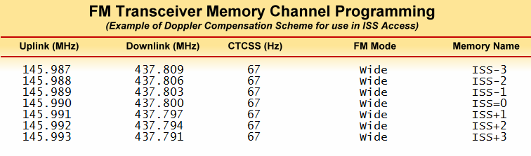
The frequency programming scheme that I personally use covers the 70cm downlink in 3 KHz Doppler-shifted steps, whereas, I apply a corresponding 1 KHz step shift for the 2m uplink. This scheme requires one programmed channel for the zero doppler situation where the downlink is set to 436.800 MHz and the uplink is set to 145.990 MHz. Around this channel, I have 3 more channels programmed on either side to cater for the ISS approach phase and the receding phase. This makes a total of 1+3+3 = 7 programmed channels for comfortable ISS cross band repeater access.
This is an example of one possible way of programming the memory channels of a dual-band 2m/70cm transceiver for easy Doppler shift correction ob the fly as the ISS crosses through the sky. As the ISS ascends over the horizon, start with ISS-3. Thereafter, gradually switch over to the consecutive memory channels like ISS-2, ISS-1, and so on. ISS=0 is for use with the point of maximum elevation of the ISS. Thereafter on the receding phase, switch to ISS+1, ISS+2, and finally ISS+3 as it nears the horizon on the descending leg of the pass.
See the chart above. You may adapt it the way you might want. Instead of the 3/1 KHz step scheme, you may opt for 5/0 KHz or any other combination. However, remember that opting for steps that are finer than 3/1 provides no additional benefit other than making it more complicated. Remember that each programmed step must include the required CTCSS frequency, which is 67 Hz in the case of the ISS repeater. - How much uplink TX power do we need to trigger the ISS FM repeater? ...Not much... Remember that the ISS downlink on a 70 cm band typically uses a 5W FM transmitter onboard the spacecraft. If the 70cm downlink can reach us with 5W, then the 2m uplink will certainly reach the ISS with a far stronger signal if we also use 5W FM TX power on our rigs. As we discussed earlier, the free-space transmission path loss on the 2m band is approximately 9.42 dB (say 9 dB) less than what one might get on the 70cm band.
Assuming the uplink and downlink antennas that we use with our rig at our QTH are similar with similar gain performance and we use 5W TX, our uplink signal to the satellite will be +9 dB stronger in comparison to the ISS downlink signal that reaches us. Therefore, if the ISS downlink can even barely break the squelch on our rig, rest assured that the ISS would be receiving your uplink signal nice and strong.
In case the ISS transmission is not heard, then the remedy does not lie in increasing the TX power at your end. With excessive uplink TX power, you might end up causing unnecessary overload or saturation of the ISS receiver front-end. However, this will not remedy the problem of not being able to copy the downlink signal because the ISS will not increase its TX power but will continue to use the fixed 5W.
Therefore, never increase the ground station TX output power beyond the normal limit of 5-10W at the most. However, working the ISS with as low as 1W is comfortably feasible. If you can't hear the bird, then the solution is not to increase your TX power, but to use a better antenna system than what you were currently using. - The next important thing is to adjust the squelch on your rig. Most VHF/UHF FM radio rigs have their factory default squelch level set pretty conservatively halfway on a scale of 1-5 or 1-10. Usually, these settings work nicely for terrestrial communication, however, to work the satellites, it is advisable to reduce the squelch level so that the FM rig could break-in even with a far weaker signal. I suggest that you set it to the lowest point where it would just barely begin to kick in on the average ambient noise at your location.
The enhanced squelch trigger sensitivity is important while working satellites as it would break squelch even on very weak and perhaps uncopyable signals from the satellite. The moment you discover that the squelch has started to break, it's time for you to quickly double-check and set Doppler correction to improve SNR, or to adjust your antenna orientation or polarization to maximize the satellite signal and improve FM quieting levels. Thereafter, you are good to establish contact. - Here is another little tip for the newcomers getting started on satellites with the use of portable handheld antennas. This could either be a whip antenna mounted on an HT or a lightweight, hand-held, dual-band yagi.
Please bear in mind that unlike small amateur radio LEO satellites that often lack any kind of worthwhile attitude stabilization and therefore roll, spin, and tumble through space resulting in total mess up of any polarization predictability; the ISS is a fully stabilized space platform with a robust 3-axis attitude stabilization.
Yet the signals to and fro the earth station and the ISS do not preserve their polarization in entirety. The ISS uses onboard linear polarized antennas, yet there is no sure-shot way of predicting the polarization of signals. Extraneous influencers like the phenomenon of Faraday Rotation is one of the major factors that alter signal polarization drastically. Check out my article on the subject Space Radio Propagation.
In other words, one would never know in advance the polarization of the received signal. One solution would be to use a circularly polarized earth station antenna for both the uplink as well as the downlink. Although, since the ISS antennas are linearly polarized this will result in an effective 3 dB gain reduction on the earth station side of the link, but this is positively compensated by the fact that the deep fading effects on account of cross-polarization loss are eliminated. The signal level is now more-or-less stable and constant. For a circularly polarized antenna arrangement, you could use either RHCP or LHCP. contrary to what one might tell you, the choice of RHCP or LHCP simply doesn't matter, at least in the case of ISS.
However, if you were to use a hand-held dual-band Yagi, then you will have to be mindful of deep cross-polarization loss that might occur if the polarization mismatch is greater than 60-75°. Thankfully, the polarization mismatch loss at 45° or less is below 3 dB. Hence, while pointing the hand-held yagi at the satellite, a slight twist of the wrist along the boom axis will alter the antenna polarization. This will allow you to maximize signal strength in real-time as the satellite flies across the sky.
If you are using an HT-mounted whip antenna, then you do not have much control over the polarization of your antenna. You could, however, make some difference and maximize the signal by tilting your HT in various directions to get a better signal. One thing that you must keep in mind is that don't point your whip antenna towards the satellite. That is the direction of the least signal emission. The whip antenna is a highly compromised and a rather inefficient equivalent of a proper 1/4λ vertical ground-plane antenna, yet the general behavioral attributes of the whip remain similar. Therefore the emission is mostly on the broad side of the element and not along its axis... The bottom line is, do not be tempted to point your whip antenna at the satellite. It would be the worst thing that you could do. Don't use your antenna as a shotgun...
The Concluding Touch...
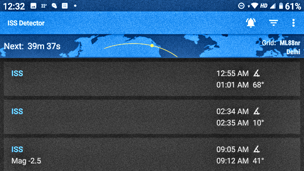
The illustration depicts the typical opening screen view of the ISS Detector App. It provides real time ISS pass positions on a map as well as on a Polar Sky view.
Along with the modest set of equipment and also the information we gathered in this article, we are almost set to go. However, we do not yet know as to when and wherein the sky will the ISS appear. When should we be QRV? The ISS passage time will be different for each different location on earth. Hence, when the ISS appears over your QTH, it may not exactly be the time when it appears over someone Else's QTH. Hence, we need a reliable method of predicting and following the ISS orbital passes.
There are many freely available software with varying degrees of complexity that are designed to do exactly that. However, we will leave them aside for the time being. We do not want anything that might be too elaborate or might need to run on a PC. Nor are we concerned with the orbital predictions of other satellites apart from the ISS. We need lightweight, free-to-use, and portable software that predicts ISS passes. Moreover, it would be most convenient if this software app could run on our mobile phone that we usually always carry with us.
We have an app that perfectly fits our requirements. It is called the ISS Detector application and is available from both the Google Play Store for Android and the Apple App Store for iOS devices like the iPhone. The free version of the app is good to forecast ISS passes, whereas, the paid version can handle almost all amateur radio satellites. However, at present, we do not need to worry about any other object other than the ISS... Download and install the app on your phone. Now you are truly geared up to take the plunge and begin to enjoy the world of ISS cross band repeater communications... Happy ISS DXing...


(13 votes, Rating: 4.77) - Please vote the article with your valuable star rating. Thanks! Basu (VU2NSB)


SSN SSNf(10.7) – Real-time Solar Data


