

VHF-UHF Radio Repeater Site Location vs Coverage
Needless to say, depending on the topology of the land, at certain places, the best choice of a radio repeater site might be obvious and quite intuitive. For instance, a city with a hill on the outskirts that is visible from all across the town would be an ideal choice. Similarly, a suburban or rural area on a plain terrain could be served sufficiently well by a radio repeater that might be installed centrally within the desired coverage area perimeter. The repeater antenna could be a high-gain omnidirectional vertical collinear array installed on a tall tower so that it could provide adequate clearance above buildings, natural or man-made artifacts, and other topological features within the desired service area. However, repeaters meant for urban coverage may be an entirely different story…
Basic VHF-UHF Radio Repeater Coverage
Ideally, an amateur radio VHF-UHF radio repeater system is meant for regular and reliable coverage within its designated service area. This means that the repeater should be accessible as often as possible using normal hand-held transceivers (HT) as well as vehicle-mounted mobile radios. Of course, there will be several shadow areas within the city due to buildings, other metallic or concrete structures, etc. However, these shadow areas should not overwhelm the coverage area percentage.
Although most good radio repeater sites generally conform to the above, yet there are many cases where the repeater installation falls woefully short of these requirements. The general rule should be that any user within the intended coverage service area of the repeater should be able to access it, if not with a portable or mobile radio, at least with a regular base-station setup using a simple 1/4λ ground plane antenna mounted in the clear outside his premises. In rare instances, one might perhaps need to set it up higher, on the rooftop.
If anything more elaborate than this is needed, then it might be fair to assume that the choice of the radio repeater site is perhaps rather inadequate. For instance, in the case of a few repeater installations, I have come across several operators located within the primary coverage area, who need to use various types of high gain vertical collinear antennas with several 1/4λ, 1/2λ, or 5/8λ collinear sections. Some people even use a multi-element Yagi antenna pointing towards the repeater. Using such high gain antennas is fine if one were to do VHF-UHF DX or access non-local outstation repeaters. However, to access a local radio repeater, one should never need to use these high gain antennas. It only means that the repeater in question is sub-optimally located.
Typical Urban Radio Repeater Site Location Issues
The usual repeater site location issues generally tend to become far more stubborn in an urban area context. Especially, in large metropolitan cities, providing acceptable overall repeater service coverage throughout the city might become a tall order. However, in most case, careful planning and due diligence would help in overcoming and resolving most issues.
One of the most common problems associated with a large modern city is the high density of buildings and other structures. Unlike suburban areas, where sufficient land is available for horizontal expansion, in the urban scenario, most of the expansion and development tend to be vertical. The dense layout of multi-story and high-rise buildings across entire cities has become a norm. Moreover, unlike rural and suburban buildings, almost all urban and metropolitan structures are made of re-enforced cement concrete (RCC) with beams, columns, girders, etc. These structures are more prone to absorption and attenuation of VHF-UHF radio waves in comparison to structures made of bricks, stones, or wood. Furthermore, these buildings are tall and hence offer greater obstruction to the radio signal skimming across the top. For instance, the signal that might reach at the ground level after diffracting from the roof of a taller building would be far weaker in comparison to a shorter building due to the higher angle of diffraction.
The concrete urban jungle is pretty hostile to VHF-UHF radio wave propagation. If the city is laid out on flat terrain, then it is fairly intuitive to find an optimum radio repeater location. One needs to choose the tallest building approximately in the center of the city, mount a high gain omnidirectional collinear antenna on its rooftop after ensuring a fair clearance, and set up the repeater.
Unfortunately, many a time, matters might not be as simple as above. Let us see why…
Practical City Terrain Problems
So far we have assumed that the terrain on which the city is built is absolutely flat. However, that may not be so, for most large cities. Since time immemorial, civilizations have thrived and cities have come up near rivers. The riverbed is invariably at a lower height above mean sea level (AMSL) than the rest of the terrain around it. That’s why the river flows along its course and does not spread into the surrounding terrain. Therefore most cities have sloping uneven terrain to say the least.The first and foremost conclusion that one might draw from the above is that, for the purpose of robust radio repeater coverage across a large, sprawling, and dense urban city that might be set around a river, it would be generally wise to avoid deploying a radio repeater at a site close to the river. Such a site will invariably be at a natural disadvantage in terms of terrain height.
Other than the above, the problems might often be further compounded by less obvious factors related to terrain undulations within the city limits. Most large cities with long histories have grown over the decades and expanded considerably. As a consequence, many of these cities might have grown and expanded across subtle elevated and undulating terrain features. Some of the features perhaps might have been sufficiently leveled off for construction purposes. Despite such land leveling and cutting, the underlying undulations in the terrain features often still remain. They manifest themselves as topographical elevation gradients.
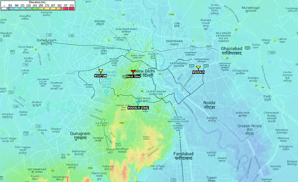
The illustration depicts the elevation Map of Delhi-NCR region in India with color-coded elevation levels. The location of various VHF repeaters discussed in this post are marked on the map.
Let me take New Delhi, the capital city of India as an example. Check out the illustrated elevation map above... This is a metropolis that has grown in size in leaps and bounds over the last few decades. The vertical growth in terms of high-rise buildings almost evenly spaced across the town has altered the landscape completely. At the same time, extensive horizontal expansion has also taken place to increase the city area by several orders of magnitude. We no more consider New Delhi or Delhi as the basic city but we now call it the Delhi National Capital Region or Delhi-NCR.
We generally consider Delhi-NCR (or Delhi) as a metropolitan city laid out on the northern plains of India... Delhi is on the plains? Yes, but it is not an absolute plain... Delhi-NCR happens to be at the edge of a nearby range of hills called the Aravalli Hills. Although the Aravalli range which is about 692 Km long and 1722m AMSL at its peak, the range is pretty far away from Delhi. It runs through the neighboring states of Gujarat, Rajasthan, and Haryana with gradually diminishing elevation. The tail end of the Aravalli range, just before merging with the plains, juts into the Delhi-NCR region from the south side of the city. This tail potion is known to the residents of Delhi as The Ridge. On average, it is about 50m above the rest of the city terrain. This ridge height at the absolute southern end of the Delhi-NCR region is approximately 90m. The height of the ridge rapidly diminishes as we move northwards into Delhi. It eventually levels out within the city.
The part of Delhi-NCR that lies on the west side of the ridge is on the average 216m AMSL. Whereas, the ridge that enters from the south and cuts through the middle heading northwards, tapers down and narrows down in width as it progresses northwards. The elevation of the ridge varies from about 295m to 250m AMSL across the south to the north. The other part of the city on the eastern side of the ridge has a sloping terrain leading to the bed of river Yamuna. The terrain gradient is from 216m AMSL down to approximately 191m AMSL at the river. The surrounding riverbed is plain with an average elevation of 196-200m AMSL.
Hence, the Delhi-NCR radio repeater primary coverage area terrain has approximately an elevation differential of 100m. Therefore, for optimum overall coverage, the best repeater site would lie at a location that is somewhere on the ridge region.
Check out the above details presented graphically on the associated illustration above. It is a color-coded elevation map of Delhi-NCR... Blue color indicates the lowest elevation AMSL while green, yellow, and red represent progressively higher elevations.
This map also shows the locations of various amateur radio repeater sites in Delhi. The two active repeaters VU2FUN and VU2DLR are indicated with yellow antennas. The VU2DLR repeater has been recently relocated. The earlier location is marked as VU2DLR (Old) and marked with a cyan antenna icon.
I have performed terrain coverage analysis for each of these radio repeaters for the 2m (144 MHz) band and graphically presented the results below. In the coverage analysis maps of the two active repeaters VU2FUN and VU2DLR, I have also highlighted the presence and consequent influence of the ridge that cuts through the Delhi-NCR region.
Other than these radio repeaters, I have also narrowed down on the probable choice of the most optimum site location for a repeater deployment in Delhi that could cover the entire Delhi-NCR region with strong signal density. This location has been marked as Best Site on the map and is displayed with a red antenna icon.
Coverage Assessment of VHF Radio Repeaters in Delhi-NCR, India - Example scenarios
Let us now look into the actual projections of our coverage area assessments pertaining to each repeater. In my analysis, I have accounted for various natural topological features in the Delhi-NCR region including their true elevation profiles. Various other factors that determine propagation loss and path attenuation have been factored in. Here is a list of some of the common factors applicable to each projection scenario.
- The atmospheric condition of the lower Troposphere has been assumed to be normal with the Tropospheric refractivity gradient pertaining to Standard Atmosphere @ -39N/Km gradient.
- The projections do not account for occasionally occurring anomalous conditions like super-refraction, sub-refraction, trapping, or ducting.
- The overall signal attenuation from the radio repeater locations to each pixel coordinate point on the map has been computed and plotted as color heat maps.
- For the purpose of computation, the curvature of the earth has been corrected with an Effective Earth Radius Factor of 4/3 which pertains to -39N/Km Troposheric refractivity gradient.
- Losses due to First Fresnel zone obstruction by the surface of the terrain and urban building clutter have been accounted for.
- Topological features of the terrain, especially the ridge region results in diffraction beyond the shadow areas of the region have also been account for in the algorithm of the propagation assessment model.
- Signal diffraction across the ridge region is not strictly a case of knife-edge diffraction because the ridge has a broad top. Additional attenuation on account of this factor is also covered by the model.
- Fairly accurate land cover data of the Delhi-NCR region that provides map coordinate data of buildup structures, forest areas, and vegetation have also been included.
Let us first take a look at the coverage assessment maps of the two currently active repeaters, the VU2FUN and VU2DLR. The map illustrations presented below for each of these sites also show a highlighted flashing overlay of the Ridge region that cuts through Delhi-NCR from the south. This will make it easy for the readers to visualize and make sense of the large additional attenuation of the signal that one would see for the part of the town lying on the other side of the elevated ridge. The propagating signals from the repeaters have to cross over the elevated ridge to reach the other side of the town. A clear correlation of the diffraction losses over the ridge can be visualized.
One might also notice that the topology of the ridge is such that it gradually tapers down in width as well as there is a reduction in elevation as it penetrates northwards. Review the first illustration of this article.
The first two scenarios for the active repeaters (VU2FUN and VU2DLR) will be followed by two more projections. One would be the VU2DLR repeater when it was operational from its earlier location. The fourth and the last projection will be, pertaining to what in my view, would be the optimum repeater site from the perspective of the best overall coverage of practically the entire Delhi-NCR region. Moreover, this location would also produce strong signal strength across all regions despite the elevated ridge running through the city. For the purpose of this post, I have termed this site location as Best Site.
Please take note of the following before you proceed to examine the Repeater Area Coverage Projections...
VU2DLR VHF Radio Repeater, Delhi, India - (28.62567 N, 77.35969 E)
True to our expectations, on account of the VU2DLR location on the east side of Delhi-NCR, the projected coverage strongly favors regions lying on the east side of the Ridge. The significantly enhanced signal attenuation across the ridge on the west side shows up perfectly as expected. Moreover, the VU2DLR repeater is located at a site that is close to the Yamuna riverbed at approximately 200m AMSL.
This is the VHF repeater coverage area assessment for the VU2DLR repeater in Delhi-NCR, India. Note the impact of the elevated ridge region that juts in from the south side and cuts across a large part of the city. This ridge is superimposed a flashing overlay.
VU2FUN VHF Radio Repeater, Delhi, India - (28.61709 N, 77.08519 E)
The coverage map projection for the VU2FUN repeater is also as logically expected. The ridge region also plays a spoilsport for the VU2FUN repeater by substantially attenuating signal to the eastern half of Delhi-NCR.
This is the VHF repeater coverage area assessment for the VU2FUN repeater in Delhi-NCR, India. Note the impact of the elevated ridge region that juts in from the south side and cuts across a large part of the city. This ridge is superimposed a flashing overlay.
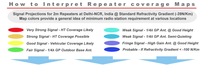
VU2DLR (OLD SITE) VHF Radio Repeater, Delhi, India - (28.53779 N, 77.18979 E)
This old VU2DLR site was perhaps that offered the best overall Delhi-NCR coverage. Although the signal strength of this old repeater might not have been as strong across the entire coverage region as one might have wished, but it certainly produced fairly good coverage across almost the entire region with good signal in most populated regions of the city. Unlike the currently located VU2DLR as well as the VU2FUN, there was hardly any area in the desired coverage region that received very weak fringe level signals... Check out the map colors. The old VU2DLR did not produce any purple or deep blue signal region, whereas both the currently active repeaters do produce large fringe areas within their primary coverage regions.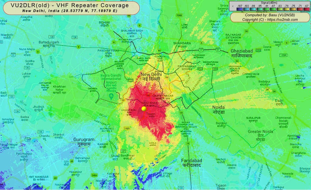
This is the VHF repeater coverage area assessment for the VU2DLR (Old Site) repeater in Delhi-NCR, India. This repeater site was located on a partially elevated part of the ridge region. As a consequence, the overall coverage across the entire region was far better that achieved from its current site.
Best site (PROPOSED) for VHF Radio Repeater, Delhi, India - (28.61543 N, 77.17608 E)
Take a look for yourself... A picture is worth a thousand words. This proposed 2m band VHF Repeater Site for Delhi-NCR would be able to produce a very robust coverage with strong signals across the entire region. A repeater at this location has the potential to truly fulfill the role of an easily accessible repeater by operators on the move. That's what a good repeater set up with due diligence must offer...
This is the VHF repeater coverage area assessment for a proposed site of a VHF repeater in Delhi-NCR, India. This site is at clear elevated location in the central part of the desired service area. The expected coverage would result in strong signals all around.
Currently, neither of the two VHF repeaters of Delhi are able to offer the much needed wider coverage. The primary intended coverage area of any repeater must fulfill the objective of adequately covering at least 90-95% of the intended territory with reasonably strong signals and should be devoid of unacceptable terrain obstruction losses. Neither the VU2FUN nor the VU2DLR is capable of doing that.
Although both these repeaters can be reached from anywhere in Delhi-NCR with a base-station setup and a low takeoff angle, and a high gain antenna with a gain of at least 5-6 dBi or more and installed fairly high above the ground level with adequate clearance all around the antenna, but this is not how it should be. It is certainly not how a local repeater should need to be accessed. This is more like working fringe DX.
A repeater must be accessible within its primary coverage area using simple antennas like the 1/4λ GP even from portable and mobile platforms. Of course, due to the clutter of buildings in a dense urban area, the coverage may not be solid at all places and at all the time. There would be many instances of deep shadow areas behind tall buildings, congested alleys, etc. However, the bottom line is that by moving out of the shadow of such local obstructions, the far-end mobile radio operator should be able to regain repeater access with ease.


(10 votes, Rating: 5.00) - Please vote the article with your valuable star rating. Thanks! Basu (VU2NSB)


SSN SSNf(10.7) – Real-time Solar Data


