

The fundamentals of Digital modulation for radio
In this article, I will attempt to walk you through some of the basics and also take a look at the genesis and evolution of digital radio communication. The average radio amateurs who come from various academic backgrounds and may not have an electronic or electrical communication leaning often find it difficult to relate themselves to the stereotypical explanations of the various nuts and bolts of the digital communication model. The objective is to keep this narrative intuitive and simple without dwelling into the associated mathematics as much as possible. Other than the use of digital modulation methods to implement digital voice communication and file transfer of documents, images, etc, the most common digital modulation methods have been used very effectively to implement text mode communication.
It is sometimes felt, especially amongst a significant section of the amateur radio community that the digital text and data modes of radio communication uses special RF modulation methods in the transceiver in comparison to what is done to produce analog radio transmissions. This is not entirely true. Let us try to clear the mist and examine the important fundamentals as we go along.
Is it Digital Carrier modulation or Sub-carrier modulation?
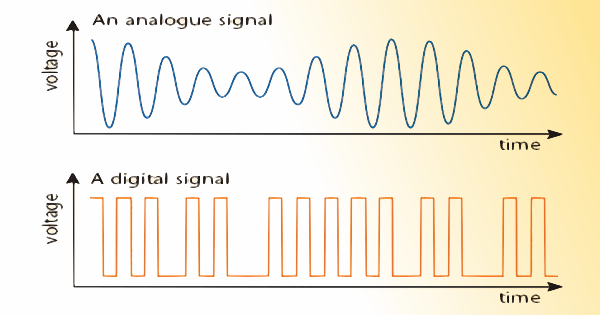
Typical shape of an analog and a digital waveform as night appear in time-domain on an oscilloscope display.
It is the payload at the input of the transmitter modulator that contains digitally coded information. Rather than a proportionately time-variant analog payload like a varying voltage that follows the voice as in the case of radio-telephony, the input to the transmitter, in the case of the digital payload has only a few pre-defined discrete levels. For instance, in the case of a binary digital data stream, there are only two discrete levels of signal voltage transition.
How can we efficiently modulate a digital data stream comprising of these discrete voltage levels? Although theoretically, we could directly modulate the digital data directly in a typical SSB transmitter, that will only produce a train of pulsed RF bursts from the transmitter. This would result in a not-so-efficient modulation method. The modulation type would be restricted to On-Off Keying (OOK) or what we might call Amplitude-Shift Keying (ASK).
To make digital modulation more flexible, robust, and immune to noise and data stream corruption, the modern digital modulation methods resort to other means. Typically, we choose to replace the audio (AF) input to the transmitter that would normally come from a microphone in the case of radio-telephony with a specially processed audio frequency signal that we call the digitally modulated AF sub-carrier.
Digitally modulated AF Sub-carrier
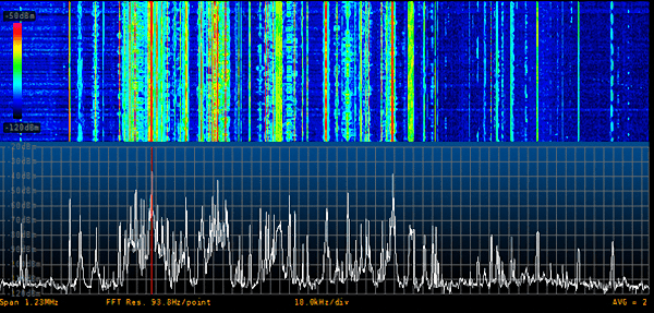
A waterfall display image of a section of HF radio band showing a concentration of several adjacent digital text-mode radio signals.
Due to the vast flexibility offered by sub-carrier modulation, today we have at our disposal hundreds of modulation variants. Many of these have attained widespread acceptance and have been duly standardized. For instance, as we are all familiar, we have PSK31, PSK63, RTTY, AMTOR, PACTOR, MFSK, MSK, MT63, GMSK, QPSK, QAM, M-ary modes, Contestia, Hellschrieber, Olivia, FT4, FT8, WS65, FSK441, etc, etc… and the list goes on. Each of these digital modulation protocols have their unique strengths and limitations. Therefore, they are used under different types of communication environments and conditions. One thing that they all have in common is that they all resort to sub-carrier modulation of an AF tone and restrict their bandwidth to the narrow baseband channel bandwidth of a typical analog radio communication transceiver.
The data-carrying capacity of a digital channel is determined by its bandwidth and the desired SNR in a noisy communication environment at the receiver end. This is well established and governed by Shannon’s mathematical theory of communication or more precisely the Shannon-Hartley theorum. Going into the details of Shannon’s theory is beyond the scope of this article since it would involve quite a bit of mathematics but for the moment it would suffice to know that there is a trade-off between the quantum of data (information) or the rate of data carried by a communication medium and the specified bandwidth. In the case of amateur radio, where the typical bandwidth of the AF baseband determines the limits of the sub-carrier bandwidth and consequently the upper limit of data-carrying capacity.
What are the options for digital sub-carrier modulation?
After having introduced the concept of sub-carrier modulation for digital radio, let us examine as to what are the parameters of a typical AF sub-carrier to achieve desired results. An unmodulated AF sub-carrier is just a pure homogeneous sinusoidal (Sine) wave at a discrete audio frequency. The sub-carrier by itself carries no information. The information (data) needs to be loaded (modulated) onto the sine-wave sub-carrier so that it can piggyback itself onto the sub-carrier and ride along. It is like riding on horseback where the sub-carrier is the horse and the digital data (in our case) is the rider or the payload.
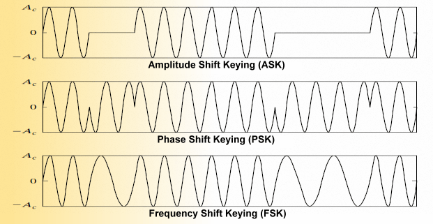
An illustration to depict the structure of typical ASK,, PSK, and FSK modulated sub-carriers.
What are these three parameters of the electrical sine-wave? They are the amplitude, the frequency, and the phase. modulating any of these three parameters effectively modulates the sine-wave and allows it to carry the information payload as piggy-back.
Physical electronic hardware circuits, as well as mathematical algorithms that run on computers, may both be used to obtain the necessary parametric modulation of the sinusoidal sub-carrier. For the purpose of typical amateur radio digital sub-carrier modulation, it has now more-or-less become a standard practice to use computer software to do this rather than to use dedicated electronic hardware. To get further clarity, let us examine a few typical digital radio modes. For instance, the well-known RTTY modulates the frequency parameter of the sub-carrier to produce frequency deviations from its original value in accordance with the binary voltage levels of the RTTY code. This results in what is known as frequency-shift keying (FSK). Similarly, PSK31 (binary phase-shift keying BPSK) which is also very common, instead of varying the frequency per se, varies the phase of the sub-carrier. This is termed phase-shift keying (PSK). In both these cases, the amplitude of the sub-carrier remains constant and hence they are often called constant Envelope modulation modes.
The average or RMS power of the modulated signal remains constant during transmission. These modes are far more immune to unwanted degradation of data integrity because the radio noise typically alters the amplitude of the RF far more than the phase or frequency of the signal. In the case of FSK or PSK, even though the RF transmission channel might have been subjected to the onslaught of a noisy propagation environment, it is easier to segregate and eliminate the noise at the receiver end and retrieve the original quality sub-carrier. Amplitude shift keying (ASK) is rarely used for machine-generated digital modes, however, the traditional CW morse code transmission over radio uses ASK (OOK).
Before we move on, let us also recognize the fact that digital data for radio transmission may not always be binary. Multi-level or M-ary data streams are also often used in some of the methods to pack more information by enhancing the effective data throughput. Though these methods have their own merits, they also usually have a downside of being less immune to noise interference.
The Digitization Process
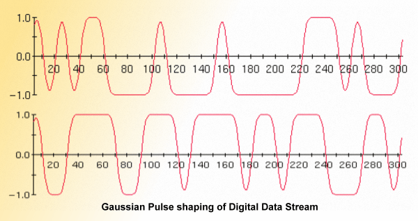
After digitization of an analog signal to convert into its binary digital equivalent, the pulse data stream undergoes a pulse shaping process before applying it for sub-carrier modulation. This results in minimization of spurious harmonics and optimization of required modulated sub-carrier bandwidth.
However, though pictures and data files may already be available in digital format if they reside on a computer, there may be instances in the case of a picture coming from an analog source like a camera that would need to b digitized before being subjected to sub-carrier modulation for transmitting over the radio. In the same way, digital voice (DV) will also require analog-to-digital conversion (ADC) on the transmitter side and a reciprocal digital-to-analog conversion (DAC) at the receiver.
These processes of converting between analog and digital equivalent or vice-a-versa, whenever needed, are done by means of various digitizing methods. The process involves sampling and quantization of the analog signal for ADC, while DAC at the receiver end may often employ a bit-weighted integrator of some form. Dedicated, high-performance hardware integrated chips, as well as efficient and fast software algorithms, are available for the purpose.
The sharp-cornered square pulses of a digital bit stream are not ideal for use in sub-carrier modulation for radio transmission. The sharp edges resulting from fast rise and fall time of the pulses generate strong harmonics that would require wider transmission bandwidth. To mitigate the situation Pulse shaping techniques are employed to optimize bandwidth requirement. These shaped pulses convey the same information, yet they use smaller bandwidths. The pulse edge roll-off (rounded) characteristics determine bandwidth. Some common methods of digital pulse stream shaping that are employed along with their typical applications are as follows…
- Root-raised Cosine (used in QPSK)
- Half-Sinusoid (used in FSK)
- Gaussian pulse shaping (used in GMSK)
How does digital modulation retain better data integrity?
Unlike analog signal modulation that essentially depends only on its inherent robustness to negotiate a hostile and noisy radio communication environment, digital modulation methods may be designed in ways to provide additional checks and balance and also quite often have some means of detecting and correcting error that might get introduced during propagation. This adds an extra dimension to digital modes and makes it attractive for radio communication.

The illustration depicts the basic process of ARQ handshaking between the transmitter and receiver during digital radio communication.
Now, the receiving side would revert back to the transmitter through Automatic Repeat Request (ARQ) and ask it to re-send the segment of the corrupted data string. The TX re-sends the data which again undergoes a parity test at the receiver. If all is fine, the RX asks the TX to send the next segment of the data stream. This process goes on continuously in the background ensuring received data integrity. This process is called Hand-Shaking. Though the received data is more reliable, the downside is that it takes additional time to conduct handshaking. This results in a reduction in effective transmission speed.
What I cited above is a very basic method. The modern digital signal transmission protocols have evolved extensively. Without going into their details in this introductory article on digital modulation, it might suffice to mention that various methods using Forward Error Correction (FEC) that do not require aggressive handshaking have been created. FEC, within its boundaries, can successfully correct a certain amount of error without referring back to the transmitter for a re-transmission. Other methods like Cyclic Redundancy Check (CRC) is often used in larger file transmissions by embedding a special code along with the data block. Hybrid schemes using a combination of several methods may also be used.
Though not applicable to amateur radio, for extreme conditions requiring uncompromising reliability where ARQ methods may not be possible as in the case of deep-space communication over millions of kilometers in space, robust self-correcting algorithms like Viterbi-decoded Convolutional codes, Golay codes, and Reed-muller codes have been used. In some instance, the concatenated Reed–Solomon–Viterbi (RSV) code have also been used. Nowadays, the Turbo code or Low-Density Parity Check (LDPC) code has been found to be extremely robust. These codes allow a high degree of data integrity in a very noisy communication environment. Their performance nearly approaches the Shannon limit of maximum channel capacity… However, that’s another story for another day.
A typical digtal radio communication transmission model?
So far we have tried to understand the basic principles behind the process of digital signal modulation by the way of its implementation using a low frequency (AF) sub-carrier within the bandwidth limits of the baseband of a typical radio communication channel. However, we now need to focus on the next step of the process that would render it viable for transmission over a radio frequency communication medium.
Please recall what we mentioned earlier. We had stated that despite the fact that the information payload at the input of the transmission chain is digital (binary) in nature, the final modulated RF that is produced by a transmitter and fed to the antenna is analog. This fact is vital and is vital and is the cornerstone of the fundamental principle of typical digital radio communication as used almost invariably, especially in the context of amateur radio.
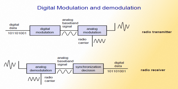
This elementary block diagram clearly depicts the modulation and demodulation processes involved in digital radio communication. The baseband sub-carrier modulation is digital while the final RF modulation is analog.
So far so good… What happens next? Now comes the time to do the rest of the magic. At this stage, we must recognize that the composition of the modulated sub-carrier is similar to any other baseband AF signal. Barring the fact that the payload content of the baseband signal rather than being voice-related AF voltage as in the case of radiotelephony, in this case, contains AF voltage swings related to digital data information. The nature of the variation of spectral composition observed on the modulated sub-carrier is quite similar to the baseband signal of a radiotelephony system.
Therefore, beyond the baseband stage, the transmitter can safely treat both analog radiotelephony signals as well as the digital sub-carrier in an absolutely similar way. As a consequence, all the technical signal handling, processing, and final modulation methods further down the transmitter chain can be (is) identical for both analog and digital radio transmission modes. The reverse but identical process is applicable in the case of the receiver on the other side of the radio communication circuit.
The bottom line is that the core transmitter, receiver, or transceiver used either for analog or digital radio communication is identical and usually the same. The transceiver architecture does not matter. A typical radio transceiver, whether it is AM, SSB, FM, or whatever can work equally well with both analog or digital baseband input signals. Digital radio only requires an additional pre-processing stage to covert (by sub-carrier modulation) a digital data stream to an equivalent AF baseband signal to conform to the specifications of a regular transceiver.
The associated illustration above clearly cites the underlying principle. An amateur radio operator making a debut into the world of digital communication needs not to feel overwhelmed or intimidated. The commonly used digital text communication in amateur radio is as simple to work as regular CW or SSB voice. The only additional factor is AF sub-carrier generation using external pre-processing software that runs on any PC. All that needs to be done is to interface a regular transceiver audio input and output using a simple cable to a PC that runs the digital mode software.
The radio rigs in the ham shack and the station antenna, all remain the same. Thereafter, one is good to go. Due to far narrow modulation bandwidths of typical digital modes, one needs far less transmitter power to establish communication using these modes. Moreover, some of these modes are highly optimized for working under weak-signal conditions thus rendering communication feasibility even under quite adverse propagation conditions.
The evolution of amateur radio digital communication modes
Over the last few decades, various digital radio communication protocols have evolved. The advent of newer digital signal processing methods and the enhancement in the processing power of a typical PC have accelerated the pace of development of digital radio communication.
In my view, digital communication has undergone generational changes over many years. I would like to classify them into three distinct generations. Though some might like to say that CW morse telegraphy was the first digital mode, I humbly beg to differ. In my view, although CW uses OOK (a variant of ASK), it is a human decodable mode. There is no digital signal processing involved in CW either for encoding or decoding. Traditionally, CW is sent using a key and the fist and decoded by the human ear and the brain. On the other hand, all digital text or data modes require a machine (e.g. a PC) to encode and decode them. Hence they are not human modes. They are machine-to-machine communication modes. It is this aspect that sets them apart.
First generation digital modes
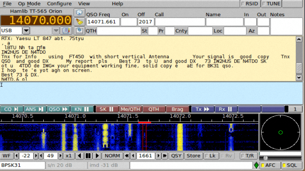
An illustration of a typical digital radio mode encoder/decoder software that interfaces to a regular amateur radio transceiver and runs on a PC to handle the entire baseband sub-carrier modulation and demodulation process.
The second type of first-generation digital mode that comes to mind is AMTOR followed by PACTOR. Both AMTOR and PACTOR have evolved from RTTY. The Amateur Teletype over Radio (AMTOR) came first. It was meant to be an improvement over RTTY. The problem with regular RTTY is that it does not have any kind of error detection or correction built into it. During transmission, those character signals that got distorted due to radio noise or interference were lost.
AMTOR was the first attempt to add a basic form of error detection and correction. After the transmission of every three characters, a parity-bit was sent for a data integrity check. The receiver would test the parity-bit integrity and then send back an acknowledgment to the transmitter with either a NAK or ACK code to let the transmitter know whether to continue to the next set of characters or to resend the earlier ones again. This is called ARQ. It led to aggressive and continuous handshaking between the TX and RX sides every three characters. This not only slowed down data throughput but also made the T/R switch in the transceivers chatter continuously leading to frequent failures. However, in all fairness to both AMTOR as well as PACTOR that were originally ARQ modes, the later variants applied FEC in its basic form to mitigate some of their shortcomings. These newer variants are called AMTOR FEC and PACTOR FEC respectively.
To minimize the aggressive handshaking requirements of AMTOR, a new improved protocol called Packet Transmission over Radio (PACTOR) was developed. Rather than verifying the transmission integrity after every three characters, PACTOR used a packet protocol. The packets are comprised of a larger set of characters to be transmitted in one go. More importantly, the packets would also include additional control blocks that contained more advanced codes for Forward Error Correction (FEC) along with ARQ. As a consequence, most of the errors that might crop in due to the anomalies of the propagation medium could be corrected on the receiver side without having to revert back to the TX for retransmission. PACTOR was also the first amateur digital text mode that supported both uppercase as well as lower case characters. PACTOR was more reliable and faster than AMTOR.
The downside of PACTOR is that it is now not an open-source mode but a proprietory mode and only one commercial entity sells the required software and hardware. Hence, the amateur radio use of PACTOR has almost vanished.
Second generation digital modes
Whereas the first generation modes were all essentially derivatives of RTTY, the second generation modes are based on entirely different thought processes. All these modes have one thing in common. They have done away with the need to resort to mid-transmission handshaking. They do not use ARQ. In other words, each round of transmission happensuninterrupted. The first and perhaps an extremely popular mode to date is the PSK31. It is a mode that neither uses ARQ nor does it provide for FEC. However, the inherent strength of the bi-phase modulation (BPSK) method used is such that PSK31 turns out to be a very robust and inherently quite an error-free mode. It uses a unique machine-readable character code format called the Varicode. The bandwidth required for a typical PSK31 transmission is so narrow in comparison to the earlier digital modes that several dozens of QSOs can be conducted within the bandwidth space required for a single SSB radiotelephony QSO.
Though PSK31 is very popular, the other second-generation modes like Olivia, Contestia, Throb, MT63, ROS, etc have also become quite prevalent in amateur radio communication. Each one of them has its own merits and demerits. Several of them also use FEC to make them more reliable under noisy propagation conditions. All these second-generation modes allow free-form text that lets the operators conduct rag chews on the air if they desire.
Third generation digital modes
With further advancement in digital signal processing technologies and aggressive application of modern and efficient FEC algorithms along with the ability to transmit and receive extremely narrow bandwidth signals to the tune of just a few Hertz for each channel, the third generation digital modes have taken shape.Due to the pioneering work by Joe Taylor (K1JT) and later also in association with Steven Franke (K9AN), several new digital communication protocols were developed that are now used by radio amateurs worldwide. New modes like JT65, JT9, FT8, etc came into being. They can all be encoded and decoded by the freely available WSJT-X software bundle created by Joe Taylor.
Originally, JT65 was developed. It uses M-ary or to be more precise 64-ary FSK protocol with an additional tone for timing purposes. Hence there are a total of 65 tones in the JT65 signal leading to its name. Although JT65 was intended to be used in scenarios like EME moonbounce, etc, it had caught the fancy of HF and VHF terrestrial amateur radio operators too.
Therefore, other variants of JT65 that were more optimized for the terrestrial radio propagation environment and the different nature and composition of noise had to be made. This led to the creation of JT9, FT4, FT8, etc. All these modes including JT65 are brilliant work of science that requires very narrow transmission bandwidths and even far narrower detection bandwidths. Moreover, they all resort to the application of very robust and efficient protocols for FEC. Due to this, extremely weak-signal communication over very narrow bandwidths become possible. The typical symbol detection bandwidths needed by some of these modes are as under…
- JT65 FSK symbol detection BW = 2.692 Hz
- JT9 FSK symbol detection BW = 1.736 Hz
- FT8 FSK symbol detection BW = 6.25 Hz
Whether it is SSB radiotelephony, CW, PSK31, or any of these new third-generation digital modes, the radio receiver’s ability to successfully demodulate the signal of interest is entirely dependent upon the noise level that exists within its detection bandwidth.
One may receive a negative SNR report down to as low as -25 to -27 dB while receiving FT8, JT65, or JT9 digital signals. Does that mean that these modes work well below the noise floor?… NO, they don’t… Received signal reports are actually referenced to a much wider noise bandwidth (2500 Hz) than the actual detection bandwidth required to successfully decode the digital data represented by the received FSK tone. The true SNR can only be found by referencing the values to the actual narrow (few Hertz) detection bandwidths for any of these modes. One will discover that the actual SNR is always positive (greater than zero).
Although a large section of radio amateurs seems to be hooked to these modes, especially FT8 on HF radio, there are a couple of major downsides. In conformity to Shannon’s theory, the data transmission rate is proportionate to the bandwidth. Therefore, on account of the very narrow operating bandwidths of these modes, the transmission speed is also extremely slow. Depending on whether it is FT8 or JT65, it would take from 15 seconds to a minute to transmit just a few characters that barely contain the bare minimum information. The shortest possible minimal QSO containing no message content whatsoever will take from 2-6 minutes to complete.
A typical JT65 or FT8 transmission would carry only the callsigns, signal report, QRA location, and perhaps a few more characters to include CQ, 73, etc as the maximum permitted payload. The transmission by these modes allows nothing more. These modes are structured modes that are non-conversational in nature. They do not allow transmission of free-form text and hence, one cannot send any messages, chat, or conduct ragchews. Although these third-generation digital modes are marvels of technology and perhaps great for occasional experimentation including testing propagation conditions, I personally find them rather mundane, zombie-like, and meaningless. They only promote mindless QSOs that have no other purpose but to acquire a QSL card.
VARIANTS of 3rd generation digital modes
The newest kid around the block is JS8 and JS8Call. We will speak about JS8Call because it offers something quite refreshing. It is similar to FT8 but it allows a conversational free-form text format thus making it more flexible and ham-radio-like. Earlier, it was named FT8Call but after objection from Franke and Taylor, the creators FT8, the author of this mode, Jordan Sherer (KN4CRD) had to change it. Hence, the name JS8Call.JS8Call comes not only with conversational capability but also features a few other goodies including a Heartbeat mode, directed calling, group calling, etc. JS8Call is still under active development and we can expect other exciting features over time.
I will cover various digital radio modes and introduce the readers to the finer aspects that could highlight and distinguish these modes and their suitability under different conditions. A set of articles related to digital modes for radio communication will be progressively added to the website… Stay tuned!


(27 votes, Rating: 4.85) - Please vote the article with your valuable star rating. Thanks! Basu (VU2NSB)


SSN SSNf(10.7) – Real-time Solar Data


