We all agree that during low SSN conditions, negotiating the HF radio bands become more difficult and stringent in comparison to what happens during the better part of the Solar Cycle. When the going is good during moderate to high SSN, a mediocre quality or even a rather poor quality ham radio station may allow one to work around the whole world, however, the scenario is quite different during low SSN. The received signals are weaker in strength. Therefore we can no more afford to get away with a noisy radio station setup. The crux of the matter is that we need to optimally reduce the HF band receiver noise floor that exists on our transceiver… If we do this, we would discover that the bands are not really dead.
I have written several articles about this earlier. I suggest that you also read those articles to attain absolute clarity on the subject and also get to know about some important tweaks that you might need to do on your station setup for overall performance improvement. I will provide links to these articles further down. Meanwhile, let us see how badly could local area noise literally render an HF ham radio station practically deaf unless we take care to minimize the receiver noise floor levels.
HF Radio station Noise Floor minimization is a game changer
Although there are various other factors that contribute to the quality of the ham radio station’s performance capabilities, it is the unoptimized noise floor level that is most destructive and can render the HF radio station practically useless during low SSN conditions. I am sure that many of our readers might still be unable to fathom the extent of damage to communication that one’s receiver noise floor could do. As they say, a picture is perhaps worth a thousand words, Therefore, I will try to drive home my point with an emphasis on graphical presentations.
Further down the article, I have presented computed map coverage of propagation possibilities that would exist at different levels of noise floor at the receiver. These propagation coverage maps have been produced w.r.t. six different ham radio station locations from around the world. These locations are spread over various continents to provide a sufficient understanding of what really happens.
The above-cited HF propagation map renditions were made for locations based in the USA, Europe, India, Africa, Australia, and South America. These maps are all based on the actual SSN and propagation conditions that were prevailing on the 3rd January 2022. The projections were done for DX openings on the 15m band on that day, during the optimum time of the day.
All station parameters were kept identical. The renditions were done with identical 15m Dipole antennas deployed at 45 feet above ground level (AGL). All other radio station parameters were kept identical. The transmitter power levels were pegged at 100W PEP for every station. The receivers had identical sensitivity and were set to identical filter bandwidths.
- ITU specified Rural Noise level (-160 dBW/Hz eq. S1 noise @ 15m) – This is the noise condition that is expected to prevail at a typical rural location with very low QRM from local and nearby electrical noise sources.
- ITU specified Urban Noise level (-145 dBW/Hz eq. S3 noise @ 15m) – This is the noise condition that is expected to prevail at a typical urban location with QRM from local and nearby electrical noise sources around us in our modern urban environment.
- HI-QRM Noise level due to poor station setup (-128 dBW/Hz eq. S6 noise @ 15m) – This is the noise condition that is expected to prevail at a typical urban location with QRM from local and nearby electrical noise sources in the modern urban environment coupled with inadequte local noise mitigation in the ham shack and a poor noisy antenna setup.
If one lives in a rural environment with a well-setup, low noise antenna system, and a low low CMC transmission line; it is enviable. The rest of us who stay in urban areas may not be so lucky, yet a good station setup will allow enough DX… However, those who live in cities and also have a mediocre/poor station setup with 15m band noise floor at S5 level or higher are classic examples of those destined for total disaster… Such people need to seriously introspect, do the right things needed to reduce the HF receiver noise floors.
HF propagation prospects at various noise floor conditions
Now, let us see how all that we have discussed so far translates into the actual HF radio propagation prospects for us. Remember, all ham radio station setup parameters have been kept identical in all scenarios presented below… The only factor that changes is the noise floor level at your receiver.
The HF radio propagation prospects for all the six cited global locations have been plotted on maps for an easy perspective. Each of the propagation map projections consists of a set of 3 map slides. One each representing the rural (-160 dBW/Hz), urban (-145 dBW/Hz), and a poorly setup HI-QRM urban station (-128 dBW/Hz) noise floor levels. The three scenarios for each location are projected as a continuous loop slide show. This will provide a quick pictorial insight into how disastrous the presence of excessive noise can be on an HF radio station’s performance… By looking at the slide-show map projections, one would definitely understand why is it that many amateur radio stations with unduly elevated noise floor levels are unable to find HF DX propagation openings during a low SSN phase… Check it out!
In all map projections below, red-orange-colored regions represent good communication prospects, yellow-green-colors represent marginal prospects, and cyan-blue-colors mean no communication prospects whatsoever.
HF propagation at USA under various local noise levels
The radio station location for the purpose of this projection has been selected in Florida, USA. The rural noise level station has a ball with remarkable openings even during low SSN. The urban station with a good setup also fairs pretty well. However, look at the scenario where the station has a poor local noise performance… The results are disastrous with little or no ability to work anything substantial on HF radio bands.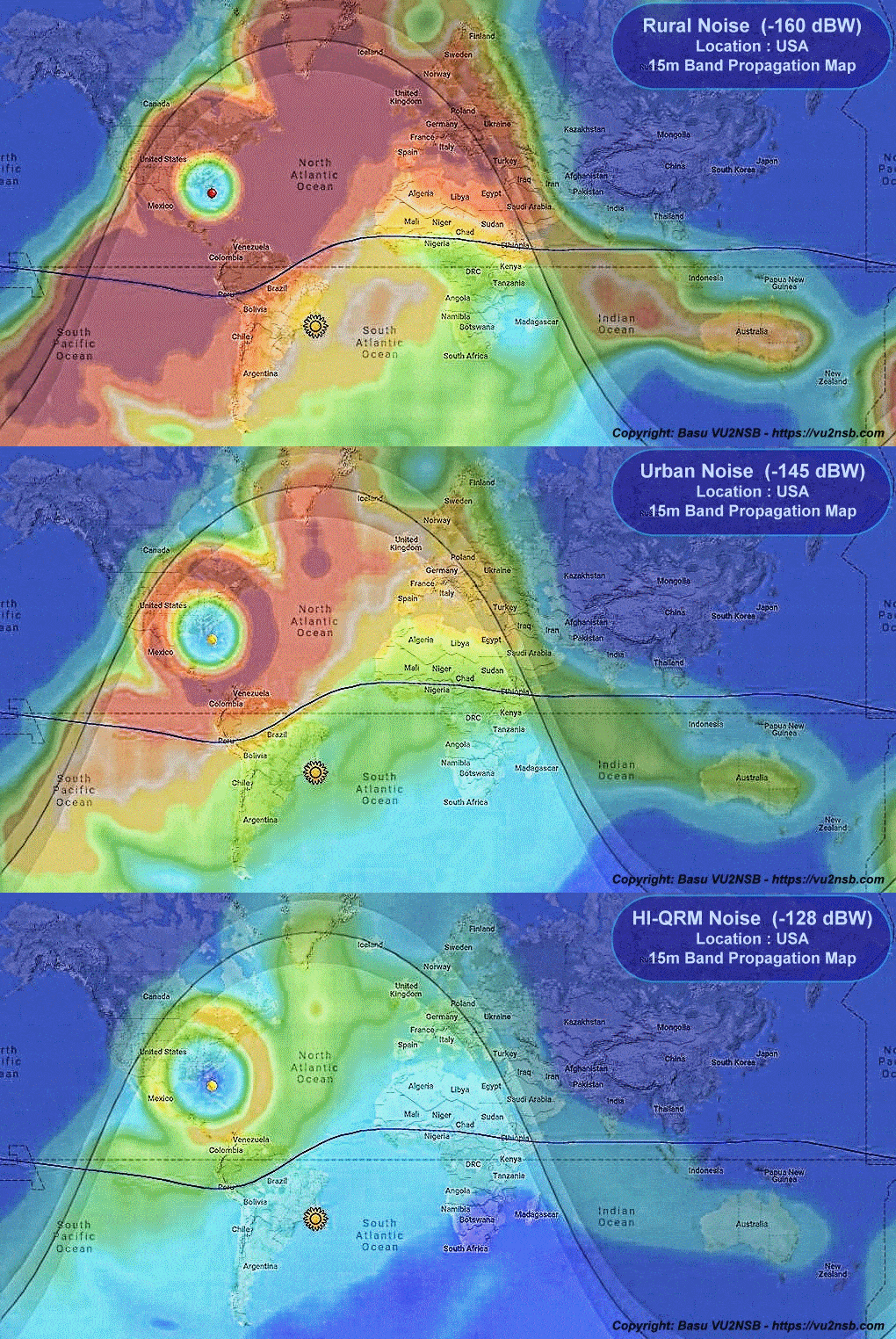
The above slide show rendition of 15m band HF propagation projection map from a location in USA. This illustrated the magnitude of communication loss that could occur due to elevated radio receiver noise floor under various conditions prevailing in rural, urban. and High EMI-RFI and noise conditions due to unacceptably high local QRM.
HF propagation at Europe under various local noise levels
The radio station location for the purpose of this projection has been selected at a location in central Germany... The interpretation of the HF propagation projections under the three noise level conditions is the same as in the scenario for USA.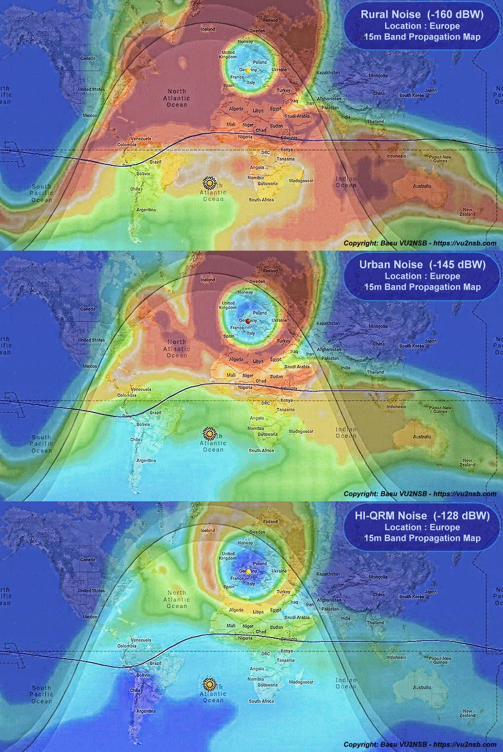
The above slide show rendition of 15m band HF propagation projection map from a location in Europe. This illustrated the magnitude of communication loss that could occur due to elevated radio receiver noise floor under various conditions prevailing in rural, urban. and High EMI-RFI and noise conditions due to unacceptably high local QRM.
HF propagation at India under various local noise levels
The radio station location for the purpose of this projection has been selected at New Delhi, India... The interpretation of the HF propagation projections under the three noise level conditions is the same as in the scenario for USA.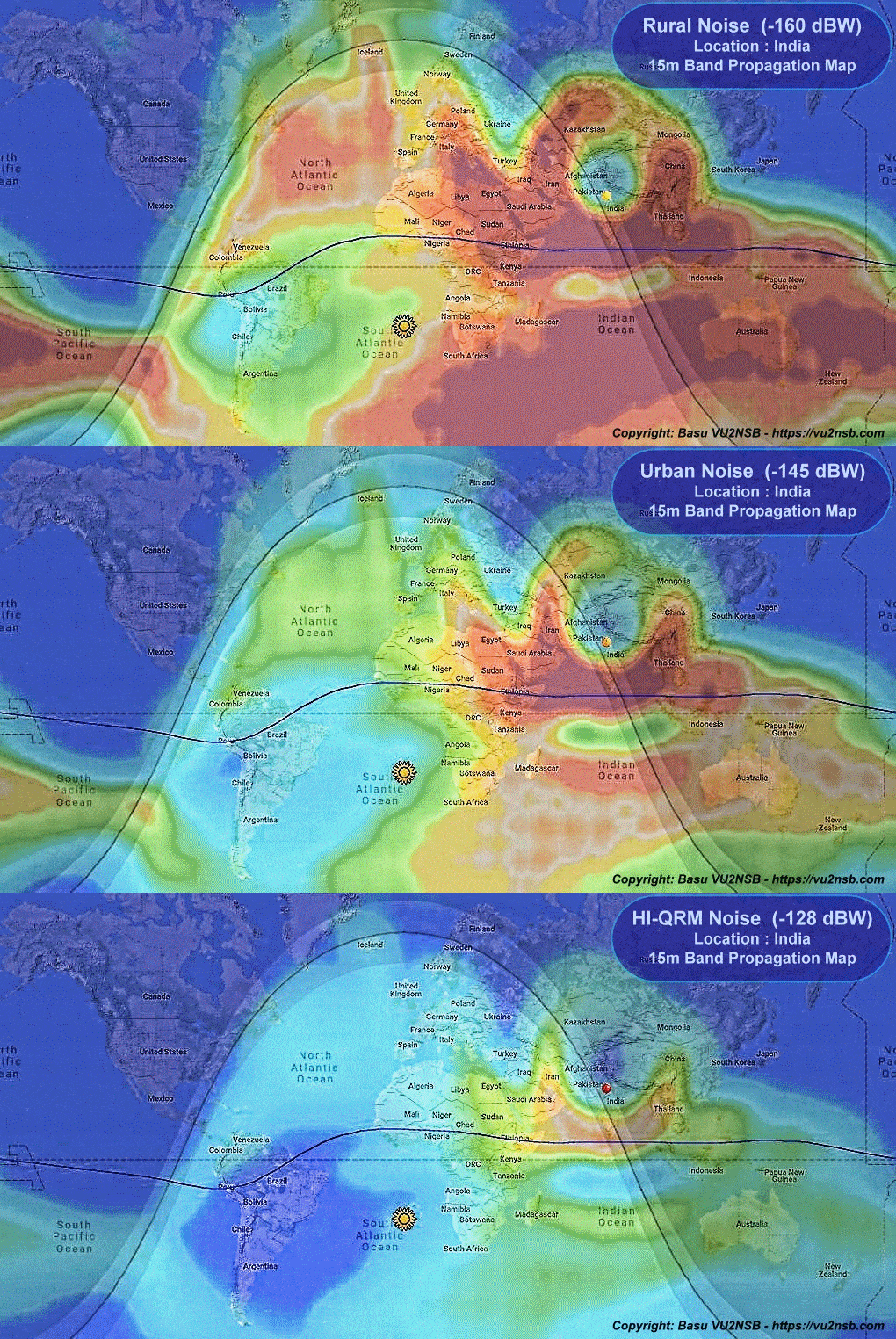
The above slide show rendition of 15m band HF propagation projection map from a location in India. This illustrated the magnitude of communication loss that could occur due to elevated radio receiver noise floor under various conditions prevailing in rural, urban. and High EMI-RFI and noise conditions due to unacceptably high local QRM.
HF propagation at Africa under various local noise levels
The radio station location for the purpose of this projection has been selected at a location in Botswana, Africa... The interpretation of the HF propagation projections under the three noise level conditions is the same as in the scenario for USA.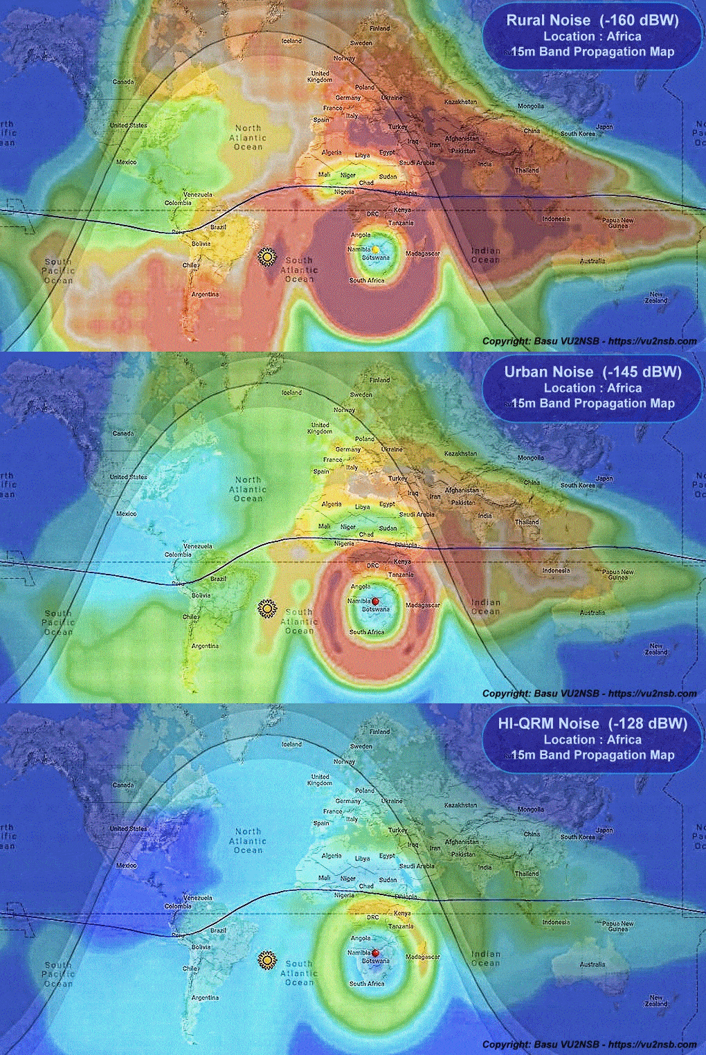
The above slide show rendition of 15m band HF propagation projection map from a location in Africa. This illustrated the magnitude of communication loss that could occur due to elevated radio receiver noise floor under various conditions prevailing in rural, urban. and High EMI-RFI and noise conditions due to unacceptably high local QRM.
HF propagation at Australia under various local noise levels
The radio station location for the purpose of this projection has been selected at a location in central Australia... The interpretation of the HF propagation projections under the three noise level conditions is the same as in the scenario for USA.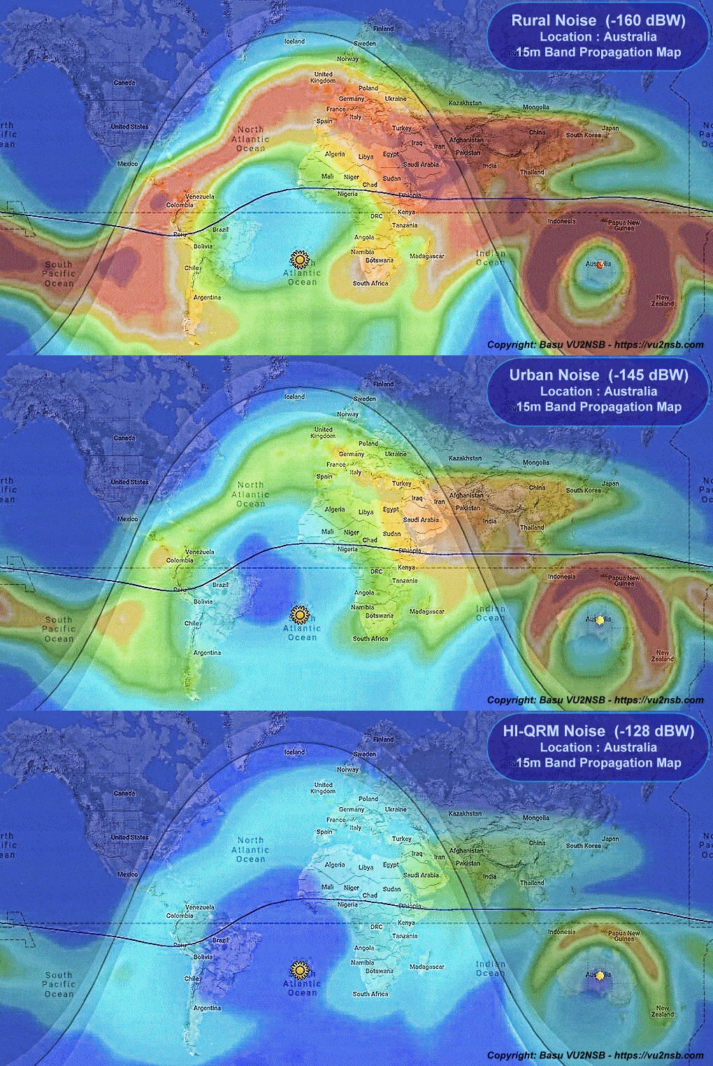
The above slide show rendition of 15m band HF propagation projection map from a location in Australia. This illustrated the magnitude of communication loss that could occur due to elevated radio receiver noise floor under various conditions prevailing in rural, urban. and High EMI-RFI and noise conditions due to unacceptably high local QRM.
HF propagation at South America under various local noise levels
The radio station location for the purpose of this projection has been selected at a location in central South America... The interpretation of the HF propagation projections under the three noise level conditions is the same as in the scenario for USA.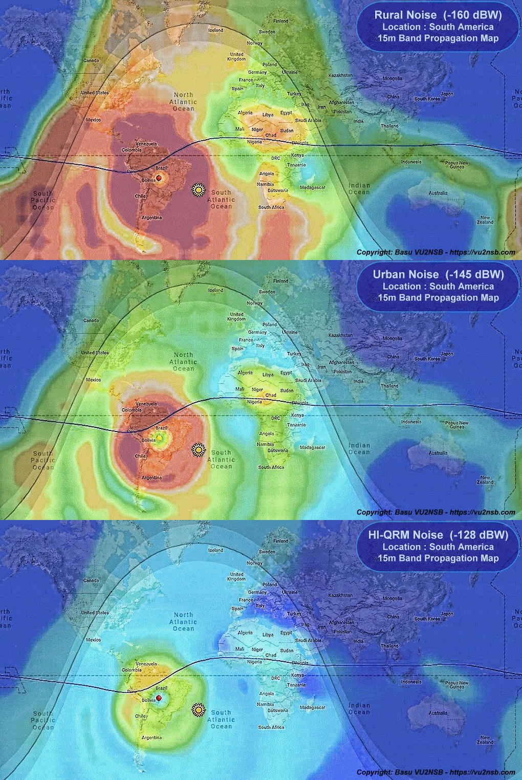
The above slide show rendition of 15m band HF propagation projection map from a location in South America. This illustrated the magnitude of communication loss that could occur due to elevated radio receiver noise floor under various conditions prevailing in rural, urban. and High EMI-RFI and noise conditions due to unacceptably high local QRM.
A wrap-up of this discussion
What we have observed above leads us to a clear conclusion. Irrespective of where your radio station might be located, it is the minimization of HF noise floor level at your transceiver that is of utmost importance. Failure to effectively address unduly high noise levels at the receiver would invariably lead to absolute catastrophe... You will then be left with no other option but to fall back on ultra-weak signal modes like FT8. You will be bereft of the real joy of work modes like SSB radiotelephony, etc... So, pay attention to any noise problems that you might have at your end and set it right! ... Unless you address the noise problems, it would be futile to go on a wild goose chase hunting for better transceivers or bigger antennas.
Noise in Radio communication - As important as the desired signal, the aggregate undesired noise in radio communication is a factor that is equally important. The insight into the causes and sources of noise are vital to determine a radio communication link feasibility and to determine its capabilities, reliability, robustness, and immunity to failure. Noise in any communication environment may arise from several sources. Therefore, it is imperative to identify and understand each of these noise sources and also to understand their characteristics.
How badly can high Local Ambient QRM affect HF Radio? - Effects of Local Ambient QRM on HF Radio Local ambient QRM (Noise) from various electrical appliances and other sources in the neighborhood often adversely affect HF radio communication. The negative effects of local QRM on an HF amateur radio station’s overall capabilities are usually far more pronounced than what most operators realize. The ability to address these noise issues may either make or break the radio station’s DX coverage efficacy. In the modern day-n-age, radio amateurs who live especially in urban and suburban areas are plagued with these adverse effects with several orders of magnitude greater nuisance value than the old-timers who operated several decades ago.
Low SSN – Why do most Hams find HF Radio so difficult? - It is true that most ham radio operators around the world in their quest for DX on HF radio find it exceedingly difficult during low SSN conditions at Solat Cycle minimas. Currently, as I write, we are negotiating low SSN conditions as we are making a transition from Solar Cycle #24 to #25. I agree that the difficulties are much greater during this phase in comparison to the high SSN phase. However, the question that is often asked is, are the HF bands practically dead? … The short answer is NO! Can we still continue to make adequate radiotelephony SSB and CW DX contacts on HF during low SSN? …YES!
Radio Transceiver S-Meter – Pitfalls to avoid - An S-meter of an HF radio transceiver is a very important instrument on the rig and is used extensively for signal reporting by amateur radio operators while in QSO. However, unfortunately, its calibration accuracy appears to be on the lowest rung of priority for the commercial manufacturers of amateur HF radio equipment. The calibration of the S-meter of most HF transceivers (including several well-acclaimed rigs) is absolutely appalling, to say the least.
Interpretation of S-Meter Noise Floor in HF Radio Receivers - I will focus on the interpretation (or perhaps misinterpretation) of the S-Meter Noise Floor levels as they prevail on HF radio receivers of typical transceivers used by amateur radio operators. Over the past year, I have covered various aspects of the difficulties that are often faced while negotiating propagation conditions on the HF radio bands. This is especially true during the current bottom phase of the Solar Cycle as we make the transition from cycle #24 to #25.

Contents
- 1 EMI-RFI and Noise related HF Radio Station performance loss
- 2 HF propagation at USA under various local noise levels
- 3 HF propagation at Europe under various local noise levels
- 4 HF propagation at India under various local noise levels
- 5 HF propagation at Africa under various local noise levels
- 6 HF propagation at Australia under various local noise levels
- 7 HF propagation at South America under various local noise levels


