

An Introductory Primer on Radio Propagation
In any form of communication scenario over geographic space, the transmission of a signal from one point to another is the fundamental objective. Radio communication systems achieve this objective by exploiting the transmission and propagation behavior of their primary propagation medium which is the free space. The radio waves or the electromagnetic (EM) waves travel through the atmosphere above the earth from one point to another across the terrain. In the case of satellite or outer space communication, these radio waves travel over long distances transcending the limits of the atmosphere and propagating through the vacuum in outer space.
Transmission and Propagation

RF wave transmission and basic propagation
There are several different propagation modes and methods that manifest themselves to enable effective communication. HF radio waves have the amazing ability to travel across thousands of kilometers around the world with very little transmitter power if the correct frequency band is selected for the desired radio circuit route. The optimum frequency for a radio circuit path also depends on the time of day, season, the activity of the sun and the geographic location of the HF radio stations.
After leaving the transmitting antenna the HF radio wave spreads out through the atmosphere or the free space as it propagates in various directions using many different methods. Some of the radio waves travel in a straight line between two visible points up to distances limited by the horizon. While some others travel along the surface of the earth by clinging to the earth’s surface and have the ability to travel across longer distances far beyond the horizon.
However, the most predominant method of HF propagation stems from the presence of several spherical electrostatic charge layers of ionized gases around the earth at varying heights ranging from 90-350 Km above the earth’s surface. These ionized layers of gases in the upper layers of the atmosphere called the ionosphere are responsible for the unique trans-global propagation capabilities of HF radio waves. When radio waves use the ionosphere for propagation they bounce back and forth between the ionosphere and the earth in either multiple hops or a single hop as required by the distance between two communicating radio stations.
We will expand on all the above-mentioned factors and much more as we progress through this article, however, at this moment we will start by examining the basic building blocks of intuitive high school physics that are applicable to radio propagation. We will touch upon the concepts as we begin our journey through the fascinating world of radio wave propagation, unraveling the mysteries as we move on. Let us recap the following physical principles.
- Reflection
- Refraction
- Diffraction
- Scatter
- Absorption
In the narrative that follows, Let us visualize the propagating radio wave as a ray for the sake of simplicity.
Principles of Reflection
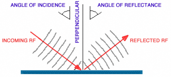
Reflection of waves from a surface
Let us see some special cases. If the medium on which the radio wave is incident is not a good conductor of electricity like earth, hill or a building, some energy is reflected back and the rest of it is absorbed. If the material of the reflecting object is a perfect conductor, almost all energy is reflected back. Hence a dry earth terrain is not such a good reflector while moist or fertile land and water bodies like lake, sea, and ocean are an excellent reflector of radio waves. The amount of energy that is reflected back also depends on the polarization of the radio wave. Of course, we will discuss the effects of polarization in-depth in our subsequent articles.
Since reflection is a rather common phenomenon that we encounter in our day to day life, it should be easy to intuitively visualize the concept. For instance, reflections from a mirror, reflection of light from flashlight from another surface, etc are quite common. Radio wave reflections also essentially follow the same physical principle. After all, there is technically no difference between a light wave or a radio wave, They are both electromagnetic waves. The only thing that sets them apart is the huge difference in their wavelengths (λ).
Principles of Refraction
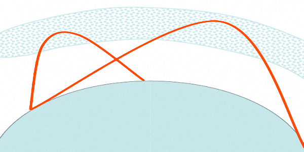
illustration of typical Ionospheric refraction
As an example, let us assume a radio wave is traveling through the Earth’s atmosphere at a constant speed and eventually comes across an ionospheric layer at several hundred kilometers above the earth. As the wave enters the dense layer of electrically charged ions, the part of the wave that enters the new medium first travels faster than the parts of the wave that have not yet entered the new medium. This abrupt increase in velocity of the upper part of the wave causes the wave to bend back toward the Earth. This bending, or change of direction, is always toward the medium that has a lower velocity of propagation. Hence this phenomenon of ionospheric refraction causes the radio wave to return back to earth at an angle.
The refraction of radio waves through the ionosphere also has the effect of gradually altering the polarization of the radio wave to a random polarization before returning it back for a downward journey to earth. This is known as Faraday Rotation. An important conclusion that can be drawn on account of Faraday Rotation is that the polarization matching of transmitting and receiving antennas is of no consequence in ionospheric skip mode communication.
Hence unlike Line-of-Sight (LOS) circuits that are so common in the case of VHF or UHF, the HF radio circuits can be set up with differently polarized antennas each end. One side can use horizontal polarization while the other can happily use vertical polarization or vice-a-versa. Trying to match antenna polarization of both stations in a long-distance (DX) HF circuit that uses ionospheric refraction for communication is pointless.
The phenomenon of refraction is the basis of ionospheric skip propagation that we will discuss in greater detail later in our discussions. Quite often many authors have wrongly or loosely attributed ionospheric skip to reflection.
Principles of Diffraction
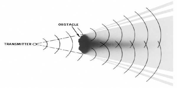
Radio wave diffraction around an object
A radio wave that meets an obstacle has a natural tendency to bend around the obstacle. The bending, called diffraction, resulting in a change of direction of part of the radio wave from the normal course of propagation. This makes it possible to receive radio signals around the edges of an obstacle. Although a diffracted radio signal is usually weak, it can still be detected by a suitable receiver. The phenomenon of radiofrequency diffraction is predominantly noticeable during radio communication conducted in a hilly terrain especially in the VHF or UHF bands.
A radio transmitter on the other side of a hill with no direct line-of-sight access can often be copied and communication can be established. Of course, other phenomena like scattering from other nearby topological artifacts also contribute to such types of communication but diffraction over or around the hilltop is one of the predominant factors. This is referred to as the Knife-edge diffraction phenomenon.
Another important effect of diffraction is its contribution towards extending the radio range beyond the visible horizon. Due to the extended range that is possible on account of diffraction, the Radio Horizon tends to extend beyond the optical horizon. This is not predominant and may play only a small role at HF, VHF, or UHF since other effects like atmospheric super-refraction, surface-wave propagation, etc usually overshadow the effects of diffraction. However, diffraction becomes rather significant at VLF and ELF frequency bands. In certain cases, by using high power and very low frequency (VLF) transmission, radio waves can be made to encircle the earth only by exploiting the principle of diffraction.
Principles of Scatter
Scattering occurs when the medium through the wave is traveling contains objects which are much smaller than the wavelength of the radio wave.
The actual received power at the receiver is somewhat stronger than that obtained by reflection and diffraction. In the microwave, UHF and VHF region scatter is caused by trees, buildings, and lampposts that scatter energy in all directions. However, for HF radio waves the primary cause of scattered signal is either the ionosphere or the earth’s surface and other terrestrial topological entities like hills and mountains.

Scattering of waves from a rough surface
Ionospheric Scatter is a forward-scatter mode occurring mostly in the lower ionosphere, at D or E layer height. It results from ionospheric irregularities and turbulence. Because signals are weak, high gain (narrow beamwidth) antennas are generally required. Normally, antennas should be aimed along the great circle path, but occasional path skewing of 10 degrees or so has been reported. We will discuss more about this exotic mode of HF communication in combination with terrestrial back-scatter which opens up a whole new world of not so well known communication sub-modes.
The scattering of radio waves is often leveraged to our advantage for VHF, UHF, and microwave communications. The well-known mode of Tropospheric Scatter mode (Tropo-scatter) allows communication on these frequency bands well beyond what one could typically expect by means of other phenomena like super-refraction, diffraction, etc. Scattering of microwave signals by dust particles or raindrops in the atmosphere often plays a vital role to either make or break a communication circuit.
Principles of Absorption
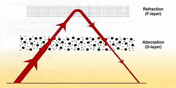
A typical illustration of signal attenuation by absorption in D-layer
The most glaring example of absorption that normally plays a spoil-sport in HF propagation is the well known ionospheric D-layer absorption of radio waves. During extreme conditions of solar disturbances like heavy Coronal Mass Ejection (CME) and multiple big solar flares, the D-Layer ionization increases to very high levels resulting in short and medium-term radio blackouts due to absorption of radio waves. Other ways in which absorption plays a vital role in accentuating radio propagation losses are on account of surface absorption of reflecting surfaces like earth’s surface, hills, and other topological artifacts.
Absorption of radio waves also occurs in the ionosphere that we depend so heavily on for our day-to-day communication use. The ionospheric layers not only refract RF signals back to earth to enable long-distance skip communication, but they are also instrumental in causing signal attenuation by absorbing a part of the RF energy. The magnitude of absorption by these ionospheric layers depends on several factors including the frequency of the radio wave and the angle of incidence of the wave as it encounters an ionospheric layer.
In the case of an HF communication circuit that has a great-circle path going over or near the polar region, the Aurora Borealis in the north and the Aurora Australis in the south often play a quite detrimental role by attenuating the propagating signal significantly. This happens more often during the times of high solar CME or when proton density and solar wind velocities get elevated. Being an amateur radio operator from India, I have encountered this phenomenon so often while trying to work North-America over the great-circle path that passes over the north or the south poles.
A brief introduction to Radio Wave Propagation Modes
Before we go to further, let us have a quick overview of the most prominent HF radio propagation modes that come in to play. Various modes that are introduced below and many others will be covered in greater detail later through subsequent articles. For an HF ham radio operator, a reasonable knowledge and understanding of methods of HF propagation is of great significance and will go a long way to make HF ham radio more exciting. We will endeavor to cover all necessary topics through various articles and posts on our website.
Direct Wave Propagation
This is the basic mode of radio wave propagation that is common irrespective of the frequency band or frequency spectrum. The Direct wave originates from the transmitting antenna and travels to the receiving antenna in a straight line. Direct wave propagation condition exists when the radio wave travels through free space without the path being obstructed or influenced by the presence of any physical object like the earth, hill, mountains or ionosphere, etc. Direct wave over the terrestrial path along the terrain is usable up to distances defined by the horizon.Since the earth is nearly spherical in shape, the higher the antennas of either or both the transmitting and receiving stations, the longer will be the propagation distance in this mode. The radio wave will normally travel further beyond the limits of the visual horizon. This is because of the fact that the underlying spherical earth caused the EM waves at radio frequencies to undergo diffraction resulting in the direct wave to bend and travel some more distance beyond the visual horizon. As a rule of thumb, the radio horizon is about 30% longer than the optical horizon at HF frequencies.
Reflected Wave
The reflection of radio wave on account of the presence of radio reflecting surfaces add another dimension to wave propagation. Radio wave reflection can occur from the earth’s surface, water bodies like lakes and oceans, hills and mountains or other man-made objects like buildings, etc. However, though these reflections often play a significant role for VHF or UHF, for HF radio, reflections from small and medium-sized buildings and other man-made structures are usually insignificant.For radio wave reflection to be prominent, it is necessary for the reflecting surface to be several orders of magnitude larger in physical size compared to the wavelength of the radio wave. In HF radio we will witness the earth’s surface and water bodies to be the most prominent reflecting surfaces that influence propagation.
Reflection of radio waves is the cornerstone of RADAR and is also used to advantage by radio amateurs for Moon-bounce or EME communication, where the surface of the moon is used as reflecting surface,
Surface Wave
This is a propagation mode that is very often loosely and incorrectly referred to as the Ground Wave propagation. This mode also has the dubious distinction of its propagation mechanism being explained wrongly in several publications and articles. A surface wave is a very interesting and complex physical phenomenon where several terrains (soil or water) property variables play out to influence its behavior. The radio wave polarization and soil surface penetration are also important factors.Surface wave radio propagation mode is very vital for effective VLF, LF and MF communication. All the MF radio broadcast stations (Mediumwave AM radio) that we listen to depend primarily on the surface waves for reliable and effective coverage. A surface wave is also very prominent on lower HF amateur radio bands like 160, 80, 60 and 40 meters. Although at higher HF bands, the coverage range of surface wave modes reduces considerably, they are present and usable. We will discuss more on this later in a separate article section on Surface Wave propagation where we will also draw the fine distinction between Ground wave and Surface wave.
SkyWave (Ionospheric Skip)
Skywave propagation mode is unique in its ability to provide trans-world communication capabilities to the HF segment of the radio spectrum. This is the predominant HF propagation mode that sets HF apart from all other frequency segments of the entire electromagnetic radio spectrum.The radio wave that starts from the transmitting antenna travels at an oblique angle into the sky to reach various layers of the ionosphere. The ionospheric layers are usually at altitudes ranging from 50 – 350 Km above the surface of the earth. There are several layers of the ionosphere which change their altitude and behavior according to the time of the day or night, seasons, etc. The ionospheric behavior also changes in accordance with the position and behavior of the radiations produced by the sun. In fact, the sun is primarily responsible for the creation of the ionosphere above the surface.
We all know that the earth is nearly spherical in shape. We can visualize the ionospheric layers as concentric hollow spheres around the earth. If we assume the earth as a sphere-shaped floor then the ionosphere would appear as the kind of a ceiling on top. It’s like a huge spherical surface with a spherical ceiling or canopy above us at a distance of hundreds of kilometers. The space between the earth’s surface and the ionosphere acts as a massive three-dimensional duct. The radio wave, if launched at an oblique angle can now bounce back and forth within this duct between the ionospheric canopy and the earth’s surface as it travels around the earth to reach a distant location in either a single hop or multiple hops as needed to cover any distance.
Let us assume that the radio wave that started its skyward journey as mentioned earlier at an oblique angle now reaches an ionospheric later. The point where the radio wave hits the ionosphere is not right above our head but a long distance away since it went up towards the sky at an angle. When the radio wave hits the ionosphere it bends back due to the physical phenomenon of refraction at the ionosphere. The angle at which it bends to start its return journey is such that it ends up hitting the earth at an even greater distance.
Just imagine a scenario that you are in a large vacant room and you throw a tennis ball towards the ceiling at an angle so that it hits the ceiling at some distance away from you. After hitting the ceiling the ball will bounce back to hit the floor further away. The ionospheric skip scenario is quite similar to the tennis ball analogy. In the case of the tennis ball, although it will bounce back from the floor once again after the first return, it may not have enough energy to go all the way up to hit the ceiling the second time. But radio waves are different. After hitting the earth on completing the first hop, the radio wave can continue along its journey through a second hop and many more, bouncing back and forth between earth and ionosphere.
Miscellaneous Modes
There are many other important and distinct modes of radio wave propagation that manifest at different times under rather special conditions. Most of them are however a combination of some of the modes we have already touched upon. They include Gray-line, Forward scatter, Backscatter, Chordal ducting, chordal hops, Sporadic-E, Meteor scatter, Trans-equatorial path, Auroral curtain refraction, ionospheric tilt, etc.Other than these, several ongoing geophysical phenomena also alter the behavior of HF communication. They include Geomagnetic disturbances, Geomagnetic equatorial tilt, and Traveling ionospheric disturbances, etc. You will find that slowly but surely, We will unravel the mysteries as we progress through the set of numerous articles that we present on our website.


(9 votes, Rating: 5.00) - Please vote the article with your valuable star rating. Thanks! Basu (VU2NSB)


Ham Rig Reviews Coming Soon
SSN SSNf(10.7) – Real-time Solar Data


