

Introduction to Radio Signal Modulation
We as radio amateurs have had the radio as a medium for almost a century in various forms and experimented with various aspects. We are all perhaps familiar with some of the fundamental aspects of the process of radio signal modulation. For instance, we are conversant with the terms Amplitude modulation (AM), Frequency modulation (FM), single-sideband modulation (SSB), etc. With the dawn of the digital age, we are all exposed to PSK (as used in PSK31), FSK (as used in RTTY), and ASK (as used in CW often as OOK). All of them are forms of radio signal modulation. Most of us take modulation for granted and rarely give it a second thought. In this article, let us try to recap some of the fundamentals of radio signal modulation and its hows and whys…
What is the need to modulate a radio signal?
Not many would ask this question. We all know the answer, don’t we? Nevertheless, for the benefit of those of us who might just be getting initiated to the world of amateur radio, let us do a quick recap.
We all agree that radio communication is used to transfer some form of information (voice, picture, text, data, etc) from one place to another distant location through an open and physically unconnected medium, without the use of wire conductors. Hence, radio communication is also referred to as wireless communication.
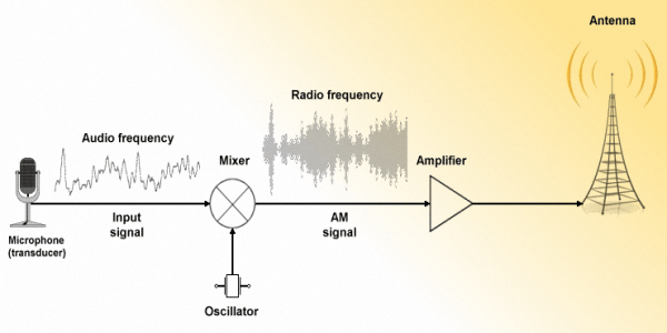
A simple illustration to depict a typical radio signal modulation method to produce AM RF signal from a transmitter.
An inquisitive reader may ask at this point since both the baseband and the carrier are electrical energies, why do we have to complicate matters by going through the process of radio signal modulation? Why can’t we simply amplify the baseband electrical signal sufficiently and then transmit it directly as electromagnetic wave using an antenna? After all, both the baseband signal and the modulated radio signal are electrical signals and hence both can be easily amplified to produce enough power. Isn’t it?
Bingo! you got it right. The above notion is absolutely correct. However, even though prima-facie it could be done, there are a few major nasty practical hurdles in doing so. That is why we opt to go via the radio signal modulation route rather than directly transmitting the baseband frequency signal… Let us see what these hurdles are.
Firstly, if all of us were to transmit our baseband audio signals, then the frequency span of all our transmissions are going to be more-or-less the same. Since the spectral frequency range would be identical, our transmissions will be overlapping and interfering with one another. That will create a mess.
Secondly, the frequency of our baseband signals will be low and fall in the audio (AF) frequency spectrum, the wavelength of our transmission will be very large. If we take approximately 1 kHz as the mean frequency of the baseband signal, it would translate to a wavelength of 300 Km. Even a typical quarter-wave (λ/4) length vertical antenna will turn out to be 300/4 = 75 Km tall with perhaps equally long radials that run in all directions around the antenna. Similarly, a half-wave (λ/2) dipole will be 150 Km long. An antenna of that size is clearly unimaginable. Even if we chose a smaller length ELF antenna that is meant for extremely narrowband signal, it will not be able to tune and operate over the wide baseband signal span from approximately required 250-2500 Hz band span.
Thirdly, even if we were to hypothetically surmount the above problems, we would be restricted only to the radio signal propagation behavior of the ELF band. We will not be able to exploit the various different EM wave propagation characteristics that are available at the higher portions of the frequency spectrum. Consequently, most of the modern-day radio communication capabilities would not be available.
All said and done, we need to use and exploit the wave propagation characteristics and other features offered by radio signals at higher frequencies like the MF, HF, VHF, UHF, and beyond. Therefore we need to have effective and efficient ways and means of transferring the baseband information on to the radio frequency signals through the process of radio signal modulation.
How is a radio frequency signal modulated to carry information?

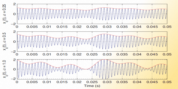
A graphical illustration depicting the nature of both the AF baseband signal and the Double sideband Full carrier AM produced after the due process of radio signal modulation.
For the modulation and demodulation process to occur, we first need to identify an attribute of the radio frequency carrier that could be continually varied in consonance with the baseband signal characteristics. Luckily, there is not only one but at least three distinct attributes of any sinusoidal RF carrier that might be used to achieve our objective. These attributes are the amplitude, frequency, or phase of the radio frequency carrier. We may choose any one of them.
When we choose to modulate (vary) the amplitude of the RF carrier in accordance with the variation in voltage envelope of the baseband signal, then the process is termed as Amplitude Modulation (AM). Similarly, if we choose to vary the frequency it is called Frequency Modulation (FM), or else, if we choose to vary the phase of the RF carrier then it is Phase Modulation (PM). Each of these three basic forms of modulation has its own strengths and weaknesses. We will discuss this in a moment… One might wonder at this point, how about SSB? Why are you quiet about it? Well, SSB is simply a variant of AM and its modulation attribute is the same as that of AM. We will focus on it in fair depth as we progress through this article.
At this point, we must understand that the RF carrier in itself does not carry any information unless it is modulated in one of the above ways. The RF carrier may be considered to like a cart that is used to ferry the information payload (baseband signal) from one location to another across great distances through the radio propagation medium.
The accompanying illustration shows how modulating an RF carrier changes the way its waveform looks. In the case of AM, one can clearly see that the amplitude of the RF carrier varies in accordance with the baseband signal envelope, while in the case of FM, the frequency of the carrier varies accordingly, and so on. The illustration should be self-explanatory.
Practical Radio Signal Modulation and their variants
Typical analog baseband signals are in the form of continually varying voltage in accordance with the original analog source. It may be the voltage output from a microphone in the case of voice, music, etc. In the case of pictures and videos, the baseband voltage signal is typically derived from camera output and so on. However, if the baseband information is digital then it might have several discrete steps of voltage levels. In the case of the commonly used binary digital information signal, the baseband voltage only two distinct voltage levels. The ongoing pattern of alteration of voltage levels between the two binary states determine the baseband signal.
The methods of modulation in the case of digital signals also remain the same as that of analog modulation. The only difference being that instead of continuous voltage level variations, we now have step variations. In the case of binary information, the number of steps is two. Therefore, the amplitude, frequency, or phase shifts produced in binary digital modulation have only two steps. Consequently, the AM, FM, or PM modulated carrier-envelope also has two levels of RF carrier-envelope variations. Since the modulation attributes of the RF carrier now appear to shift between two possible states, the digital forms of radio signal modulation are generally referred to as Amplitude Shift Keying (ASK), Frequency Shift Keying (FSK), and Phase Shift Keying (PSK) that correspond to AM, FM, or PM as applicable to analog modulation forms respectively. Find out more about digital signal modulation in the article on Digital Modulation Fundamentals.

Typical waveforms of AM modulated signal (Red) and FM signal (Blue) produced by modulating an RF carrier with a low frequency baseband information signal shown at the top (Black).
However, it is important to note that the modulation processes of all types have a method to the madness. They are not just random intuitive processes but they all have distinct and definite mathematical correlations. In other words, every form of radio signal modulation follows a mathematical model and can be expressed and defined by mathematical equations. This brings out a very interesting aspect of modulation. Not only can radio signal modulation irrespective of AM, FM, PM, ASK, FSK, PSK, or other complex variants be produced by traditional analog circuit implementations, they can also be produced by digital computer algorithms that process the associated mathematical equations in real-time.
The high-speed modern computers (including PC) or specially designed dedicated digital electronic circuits like Field-Programable Gate Arrays (FPGA), Digital Signal Processors (DSP), or Application-Specific Integrated Circuits (ASIC), etc including high-performance microprocessors may typically be used to undertake the process of both radio signal modulation and demodulation. Although the traditional methods of using analog electronic circuits for modulation and demodulation is commonly used in most of the radio equipment for amateur radio use, in the modern-day and age, more and more equipment are now being built that use hardware-based mathematical digital signal processing to achieve these objectives. Such algorithmic implementations form the backbone of Software Defined Radios (SDR).
In this article, however, I will cover only the fundamentals based on traditional methods. I will keep the narrative simple and intuitive and stress only on the core fundamentals of the concepts. Subsequently, in follow-up articles under this section, I will dwell into to the finer aspects including digital methods of radio signal modulation.
Amplitude Modulation (AM) Methods for Radio Communication
AM has traditionally been the first popular form of RF signal modulation that came into vogue. Traditionally, AM has been implemented by electronic circuits using some kind of active devices like vacuum tubes or transistors. The objective is to vary the amplitude of RF carrier that passes through an amplifier in a controlled manner by application of a control voltage which in our case is the baseband information signal voltage.
The depth of modulation determines the Modulation Index of a radio signal. A higher modulation index leads to better efficiency and more optimized use of the RF carrier for transmitting the information.
The reason for final stage modulation is that it provides the best achievable efficiency since the final PA stage as well as all the previous stages in the RF chain may work in class-C mode. Class-C amplifiers are far more efficient than other types like Class A, B, AB, etc. A similar process is applicable to semiconductor RF PA too. In the case of Bipolar Junction Transistors (BJT), the bias current control may be used, whereas in the case of Field-Effect Transistors (FET), MOSFET, LDMOS, and other modern devices, the Gate bias control in several forms may be used to achieve modulation.
However, AM might be done at an earlier low power stage in the RF amplification chain of a transmitter. This is quite a common practice in lower power radio transmitters but it is not suitable for high power transmitters like those used for radio broadcast. The reason is that after the amplitude modulation is applied to the RF carrier, all subsequent amplifier stages must be linear amplifiers so as to retain the modulation envelope characteristics of the RF without introducing unacceptable distortion.
Though unmodulated RF or even FM (as we will see later) can happily be amplified by Class-C (high efficiency) amplifiers. However, once the AM process occurs and the signal is already amplitude modulated, the following stage Class-C amplifier will destroy the envelope shape of AM signal. The only option thereafter is to use linear amplifier stages like class A, AB, etc. These classes of amplifiers are far less efficient and hence a considerably higher amount of energy loss in the form of heat would occur. The demodulation process at the receiver is rather simple for AM requiring an Envelope Detector.
Speaking of efficiency, besides the modulation process efficiency that we addressed so far, the AM modulation format itself is rather inefficient… How so?
Let us examine the content of an amplitude modulated (AM) signal. An AM RF signal contains a partial amount of the original non-information carrying RF carrier and two other spectral components called the sidebands. Since the partially retained carrier does not contain any information, it is rather useless from a radio communication perspective. Similarly, the two sidebands, the Lower Sideband (LSB) and the Upper Sideband (USB) which reside just below and above the carrier frequency, carry duplicate copies of the information that was modulated. Transmitting duplicate copies of information is redundant and not only a waste of power but also a waste of the precious spectral space on a radio band.
What does it all mean? In an AM transmitter, under the best circumstances, assuming 100% modulation depth (modulation index 1), 50% of the total RF transmitter power continues to remain in the residual carrier. This means that half of the total transmitter power output is being wasted as it does not help in carrying any information. To make things worse, both the sidebands that carry an equal amount of the balance 50% RF power carry duplicate information. Hence, only half of the total sideband power is actually needed, the other half is a waste. The 50% RF energy of the 50% contained in both sidebands is useful. The other half is redundant. This implies that overall only 25% of the total AM transmitter power is serving the useful purpose of performing the designated function of carrying meaningful information. The balance 75% of the total AM transmitter power is utter waste.
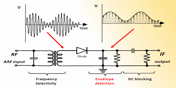
A typical AM demodulator circuit in the form of a simple envelope detector for extracting the modulated information from the radio signal at the receiver.
Let us see what happens if we begin to discard redundant components of a modulated RF signal prior to transmission. To begin with, let us discard the remnant carrier. This produces what we term as Double Sideband Suppressed Carrier (DSBSC) transmission. A DSBSC transmission is twice as efficient as the regular AM in the DSBFC format. The 50% of the RF energy contained in the modulated carrier is now removed prior to transmission. Hence, we now have a scenario where the sideband components LSB and USB remain. Therefore the DSBSC minus the carrier but with two redundant sidebands have a communication efficiency of 50% as against only 25% as was in the case of normal DSBFC AM.
If we take the process forward by another step and discard one of the two redundant and duplicate information-carrying sidebands, we would improve the communication system efficiency by another 2x factor. This would give rise to Single Sideband Suppressed Carrier (SSBSC) transmission mode. This is popularly called SSB mode. The SSB mode provides maximum efficiency of information communication because it no more contains any non-productive or redundant component of modulated RF energy. The transmitted sideband may either be LSB or USB. The corresponding receiver at the far end must also be switched to the same sideband to ensure reception.
At this stage, one might ask, if SSB is 4x as efficient as the regular AM then why don’t radio broadcast services around the world us SSB instead of AM? Firstly, to change over from AM to SSB, hundred of millions of AM broadcast receivers in use around the world would need to be replaced to make them compatible with SSB. Secondly, even though SSB does not transmit the RF carrier, to be able to demodulate SSB at the receiver it would require a carrier for reference. In communication receivers used by radio amateurs, professional, and military services, an equivalent of the carrier is generated in the receiver to make it work. This complicates matters, requires additional circuits with high degrees of stability, and increases cost. Moreover, tuning a radio station for a reception is a more arduous process in SSB that requires quite an accurate match between the transmitter and receiver frequencies. Unlike DSBFC AM, the SSB transmission sounds horrible with even a small mistuning of the receiver. All these factors make it rather unattractive to an average domestic user.
Single Sideband (SSB) Modulation Methods for Radio Communication
Let us return our focus to SSB that is perhaps the single most used radio signal modulation mode used in amateur radio. Almost the entire HF band amateur radio communication is conducted using SSB. It is also used extensively for VHF/UHF terrestrial radio communication and satellite radio after FM. This modulation mode is very robust and highly spectral efficient in nature.
Typically, on the HF radio bands, most types of communication including SSB radiotelephony, the LSB is generally used on all bands from 160m to 40m while USB is used for 20m to 10m bands. The CW mode QSO, however, is usually conducted on all bands in LSB while working as modulated CW (MCW) through SSB transceivers. There is no hard and fast rule but the above usage pattern is traditionally in vogue.
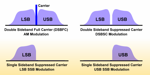
The illustration depicting the typical sidebands and carrier component of AM signal. It also shows the structure of DSBSC and SSB modes. Both LSB and USB modulated signal sideband structures are shown separately also.
We had discussed earlier the simple modulation processes that were required to achieve AM. However, the radio signal modulation process required for producing SSB is slightly more elaborate. Traditionally, there are three methods of generating an SSB modulated signal. These methods may be used both for implementing SSB using analog as well as digital processes. They are the Filter Method (First method), Hartley Modulation (Second method), and Weaver Modulation (Third method).
There is one thing that is common to all the three above-cited methods for SSB generation. It is the core modulator or demodulator block. Unlike AM, this core block typically has an additional requirement. To start producing SSB, the most important factor is to use a modulator circuit with the inherent capability to suppress the carrier component at its output. Although the SSB generation by retaining only one sideband (LSB or USB) would be done by the any of the three cited methods of SSB generation, the carrier needs to be removed by the core modulator block.
We use a circuit configuration called Balanced Modulator. The objective of the balanced modulator is to produce both the sidebands but suppress the carrier. In reality, a balanced modulator that is practically used goes one step further and is called Double Balanced Modulator (DBM). Not only does a DBM suppress the carrier but unlike a simple balanced mixer, it also suppresses the modulating baseband signal and prevents it from appearing at the output. Hence, a DBM can isolate both the input ports (carrier input and baseband input) of the modulator from the output.
There are several ways of physically realizing a DBM as electronic circuits. Passive DBM like the Ring Modulator configuration or active DBM like the Analog Multiplier Gilbert Cell configuration is quite common. Radio amateur equipment has consistently used popular integrated circuit (IC) implementation of Gilbert Cell type DMB. A very popular IC has been the MC1496. Switching type circuit configurations like Sampling Modulator or Quadrature Sampling Modulator are also good options that are often used in modern SDR transceiver designs. There are other ways of achieving the objective too. The important attribute of a DBM irrespective of how it might be implemented is that it contains only the two sidebands (LSB and USB) components at its output while having removed the carrier and baseband components.
Now, by applying the DBM in different circuit configurations, any of the three stated methods of SSB generation may be applied to produce the final SSB output.
The First Method or the Filter Method for SSB
The first method or the Filter Method for SSB is theoretically a simple way of removing the redundant sideband. The process is straightforward. In the SSB exciter stage, a DBM is used to produce DSBSC output. Thereafter, it is followed by a sharp and narrow bandwidth band-pass filter (BPF) to retain the desired sideband while it rejects the other sideband that falls outside the filter passband. Typically, quartz crystal-based filers are used since they may be configured to produce very sharp attenuation characteristics outside the passband.The sharpness of the filter boundary slopes determines what is termed as its Skirt Selectivity. Crystal BPF has very High-Q and also a fairly flat passband frequency response with low ripple. The attenuation outside the -3 dB limits of its passband is usually very sharp with a Skirt Selectivity of 60 dB/octave or even more. The filter is applied at the intermediate frequency level at the SSB exciter stage in the SSB transmitter chain. The application of Crystal (X-tal) filter is often done at 6-9 MHz in the SSB exciter.
However, in the past, quite often mechanical filters have also been used to generate filter method type SSB. These mechanical filters could only be used at lower frequencies, unlike the X-tal filters. Therefore, it was common to apply them to the output of a DBM stage that was designed to operate at around 455 kHz. This frequency was a traditional intermediate frequency of the most transceivers of the yesteryears.
The Second method or Hartley modulation Method for SSB
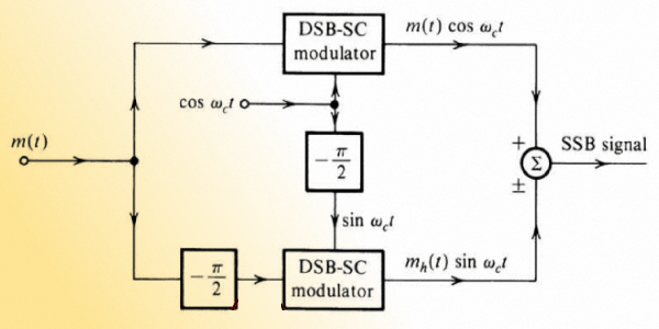
A block diagram shows the typical configuration of the Hartley modulation or second method of SSB generation using an AF broadband polyphase quadrature phase-shift network.
Nowadays, with the easy availability of low-cost components for digital signal processing, the fabrication and replication of high-performance AF baseband quadrature phase-shifters have become rather simple. A mathematical method known as Hilbert Transform that can easily be implemented using small single microprocessor chips has made it so attractive. Hilbert transform takes the sweat out of fabricating quadrature phase shift networks. A single low-cost miniature IC with ADC input and a DAC output can run Hilbert transform thus rendering a simple drop-in replacement for the elaborate RC polyphase networks of the yesteryears. No capacitors or resistors are needed anymore to implement quadrature phase-shifts.
Hence, the second method or the Hartley modulation method of SSB generation is now rather easy to implement and replicate in mass production. The Hartley method requires two DBM circuit instead of only one that is needed in the Filer method SSB. Other than the AF broadband quadrature phase-shift, it also requires a dual output quadrature (90°) phase-shifted RF carrier oscillator. The implementation of an RF carrier quadrature phase shift has never been a problem. The required circuit implementations are quite simple with very little hardware overhead. Most of the modern-day SDR follow the fundamental principles of Hartley modulation and demodulation to achieve various circuit design objectives. This includes the popular Zero-IF Quadrature (I/Q) front-end designs of many SDRs in common use.
The Third method or the Weaver Modulation Method for SSB
The third method or the Weaver Modulation Method for SSB was developed to overcome some of the difficulties in implementing the Hartley method due to its dependence on the rather difficult to fabricate analog quadrature phase shift networks during those days. Like the Hartley method, the Weaver method also does not require X-tal BPF. Furthermore, the Weaver used a clever workaround to do away with the need for AF baseband quadrature phase shift networks altogether.Despite the fact that the earlier two methods, the filter method, and the Hartley method successfully remove the unwanted sideband and other spurious within acceptable limits, they leave a very small residue due to the imperfections of a physical X-tal filter or amplitude/phase mismatch between quadrature phasing networks. The Weaver method has the inherent advantage of suppressing these spurious out-of-band adjacent channel outputs. Whatever small residue that might be left, all behind falls within the SSB channel itself and not outside it. The highly attenuated spurious reflection within the transmission channel would not be noticeable.
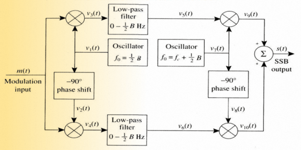
The illustration to depict a block diagram of a typical configuration for Weaver modulation or third method of SSB generation.
Despite all the good things about the Weaver SSB modulation method, it has a minor shortcoming. There is a narrow gap around the first LO 1500 Hz (B/2 Hz) sub-carrier frequency where the modulation is suppressed and we cannot hear any audio. This hardly has any implications in radiotelephony. Apparently, the human voice doesn’t carry much audio spectral energy around 1500 Hz anyway. So, the loss due to this gap doesn’t matter.
If one were to closely examine the circuit design of the Hartley and the Weaver methods, one would realize that the second half of the Weaver circuit is essentially the same as that of the Hartley circuit. The Weaver method simply replaces the polyphase type analog audio baseband phase-shift network with an alternate arrangement that no more requires the polyphase quadrature shifter.
Instead of trying to phase-shift the whole range of audio frequencies, this method modulates the baseband audio with an AF sub-carrier, which is a fixed frequency in the middle of the audio band, B/2 Hz. Two parallel sub-carrier modulated channels are created. The only difference between these parallel channels is that the sub-carrier LO frequency to each is in quadrature. The frequency translated baseband after sub-carrier modulation in each channel is therefore also in quadrature. The low-pass filters after the DBM of each channel are set to cut-off at B/2 Hz. This ensures that the input to the last pair of balanced modulators results in the proper eventual sideband suppression.
The Weaver circuit, as well as the Hartley circuit, offers a very simple way of switching the sideband output from LSB to USB or vice-a-versa. All that is needed is to flip the phase of any one of the LO to the input of a DBM by 180°… That’s it. Achieving this phase reversal is very elementary in an electronic circuit.
The third method or the Weaver method of SSB generation may look deceptively simple when compared with the Hartley (phase-shift) method but it has several finer aspects to it that I will subsequently cover in another article.
Frequency Modulation (FM) methods for Radio communication

An animation showing a typical Frequency Modulated (FM) radio wave.
Prima facie, FM appears to be easy to understand intuitively as a variation of the RF carrier frequency in relation to the modulating signal envelope as against the variation of carrier amplitude as in the case of AM and its derivatives like SSB. However, there is a lot more to FM than what meets the eye. Without going into the detailed explanation of various attributes of FM in this introductory article, we will only enumerate these attributes. I will reserve the details of FM to a separate article under this section.
Before we list out various important and perhaps not so obvious attributes of FM, let us examine the typical standards as applicable to FM radio communication, especially with regard to amateur radio. The two common factors that designate the FM standards are its Frequency Deviation (Deviation) and Channel Bandwidth. Unlike AM where the upper-frequency baseband bandwidth limit determines the channel bandwidth, the FM channel bandwidth is more complex. The FM channel bandwidth requirement is a function of not only the baseband signal bandwidth but also the chosen Deviation. The bandwidth of FM is typically larger than the baseband bandwidth and hence it occupies more space on the RF spectrum for effective transmission in comparison to SSB.
The bandwith of FM signal may be calculated by the Carson’s Bandwidth Rule as stated below…
BWFM = 2 x (Δfc + fm)
Where…
Δfc is the peak frequency deviation of the RF carrier.
fm is the highest frequency of the baseband modulating signal.
Carson’s rule is only an approximation and determines the required channel width for practical FM communication. It is not a definitive indicator of the modulated signal bandwidth. FM sideband energy is produced beyond the boundaries of Carson rule but those sideband components are low in amplitude and may be safely suppressed by application of filters.
Returning back to the topic of practical bandwidths required for various types of FM radio systems, let us apply Carson’s rule to determine their channel bandwidths.
FM Monophonic Radio Broadcast
frequency Deviation = ±75 KHz
Baseband AF Bandwidth = 15 KHz
Channel Bandwidth (Carson Rule) = 2 x (75 + 15) = 180 KHz
FM Stereophonic Radio Broadcast
frequency Deviation = ±75 KHz
Baseband AF Bandwidth = Combined (L+R and L-R) = 53 KHz
Channel Bandwidth (Carson Rule) = 2 x (75 + 53) = 256 KHz
FM Radiotelephony Amateur & Commercial Communication
frequency Deviation = ±5 KHz
Baseband AF Bandwidth = 3 KHz
Channel Bandwidth (Carson Rule) = 2 x (5 + 3) = 16 KHz
FM (NFM) Radiotelephony Amateur & Commercial Communication
frequency Deviation = ±2.5 KHz (narrow deviation)
Baseband AF Bandwidth = 3 KHz
Channel Bandwidth (Carson Rule) = 2 x (2.5 + 3) = 11 KHz
Of the above examples, the first two represent FM broadcast radio, while the last two are for typical FM voice radio communication systems as applicable to amateur radio. Usually, amateur radio FM transceiver manufacturers tend to designate the ±5 kHz deviation mode as wide FM (WFM) and the ±2.5 kHz deviation mode as narrow FM (NFM). The channel spacing with adequate guard-band needed is typically 25 kHz and 12.5 kHz for WFM and NFM respectively. Most modern amateur FM rigs allow the user to switch between these modes. BTW, an even narrower FM mode is in vogue mostly for commercial and military communication that utilizes 6.5 kHz bandwidth.
There is a move in amateur radio to promote NFM and discard the use of WFM. In Europe, I believe it is mandatory and the rest of the world is gradually following suit. There are a few points that one must keep in mind while using WFM or NFM.
- NFM transmission can be received by a WFM receiver but with reduced audio output.
- WFM transmission on a NFM receiver will sound clipped and distorted.
- Most FM repeaters now transmit NFM but their receivers still accept WFM for compatibility.
- Some FM rigs might be designed to transmit NFM but receive in WFM mode for compatibility with older equipment.
- If a NFM transmission is made to a WFM repeater then it might at times be difficult to open it with PL tone.
Some of the features and attributes of FM are as under…
- FM modulators are typically Reactance modulators, Phase-Locked Loop (PLL), or Direct Digital Synthesizer (DSS).
- FM may be generated at an early-stage low-power level in transmitter chain and be amplified by non-linear Class-C amplifiers having higher efficiency.
- FM can pass through Class-C frequency multipliers thus allowing flexibility in transmitter design.
- Unlike AM or SSB, the FM modulation index varies and progressively declines at higher baseband AF frequency.
- FM signals are inherently wider than AM signals having the same intelligence bandwidth, due to the presence of multiple sidebands.
- At high modulation index, 3–5 sidebands may contain significant fraction of signal power.
- Total FM signal power is constant and doesn’t change. The total power is continually and dynamically distributed between the carrier and the sidebands.
- The effects of noise (QRM and QRN) is minimal on FM since noise is typically AM and FM receivers can reject most AM noise components.
- FM is inherently capable of rejecting a weaker FM co-channel interference due to the Capture Effect phenomenon. However, the downside is that a stronger co-channel FM station will completely suppress and eliminate the weaker signal.
I have tried to provide a general overview of various types of radio signal modulation principles in this article. The narrative focused on typical analog signal modulation modes that are commonly used in amateur radio. For those who might be interested in some insight into various digital modulation modes might like to check out my article on Data & Text Mode Digital Radio.


(11 votes, Rating: 5.00) - Please vote the article with your valuable star rating. Thanks! Basu (VU2NSB)


SSN SSNf(10.7) – Real-time Solar Data


