

Classic miscellaneous antennas for communication
Some of these miscellaneous antennas are Cardioid pattern antennas, Four Square, Lazy-H, W8JK, ZL special, Moxon, Cobweb, Hex-beam, Bruce array, Bobtail curtain, etc to name a few. Many of them are multi-band antennas while others are mono-banders. Some of these antennas have quite unique characteristics with great performance. This is only an introductory article.
However, under this section, we will from time to time expand upon them through in-depth articles and dwell into greater depths discussing their design principles, characteristics, and practical designs. Another antenna that is designed by yours truly, called the ‘VU2NSB OmniDX” antenna will also be presented. BTW, the list of antennas cited here is by no means exhaustive. These are only a selection of popular antennas in the miscellaneous category.
Other than those I mentioned so far, there are many other antennas often used by amateur radio operators. Many of them are restricted space miniaturized types with compromised performance. Nevertheless, they offer a solution to those who might have no other options on account of space limitations and urban law restrictions. Some of these are the Hantenna, the Isotron, etc. They usually obtain their radiation characteristics by utilizing the traits of a leaky transmission line (leaky feeder antenna). The effective gain and radiation efficiency of such antennas are rather low but something is always better than nothing. When the HF skywave propagation conditions are really good and when one might normally be able to work DX perhaps QRP into a dipole, that’s when these antennas also provide ample coverage even though they may have a negative dBi gain.
Before we move on, I would also like to mention the Magnetic Loop antenna. Essentially, it is a good receiving antenna. It has a very high Q-Factor and hence has an inherent ability to reject adjacent channel interference. However, a Magnetic Loop is not really a transmitting antenna. It requires constant tuning with the change of frequency even within a band which makes it very cumbersome as a TX antenna. Moreover, It has a very high Q LC parallel resonant circuit arrangement at the antenna end requiring a variable tuning capacitor. This generates extremely high RF voltage. Due to this, it requires a vacuum variable capacitor that is rather expensive and quite inconvenient to operate. Unless one is running extreme QRP, a Magnetic Loop antenna is impractical for use by two-way radio communication stations.
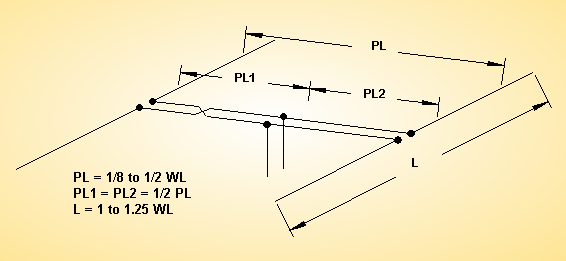
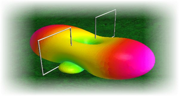
The Cardioid Pattern antenna.
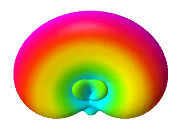
A typical Cardioid shaped azimuth radiation lobe pattern
Unlike the omnidirectional antenna that has uniform radiation around 360° azimuth, a Cardioid pattern antenna typically covers about 180-210° give and take a bit. Typically it covers one hemisphere in the azimuth plane while having a fairly good rejection on its backside with a deep null right behind it.
As a consequence, a cardioid antenna has two distinct advantages over an omnidirectional antenna. Firstly, on account of its radiation pattern shape, it offers a significant rejection of unwanted interference (QRM) that might come from the backside. Secondly, This antenna achieves a higher forward gain in comparison to the omnidirectional antenna. Depending on the geographic location of a radio station, the 360° azimuth coverage of an omnidirectional antenna may not always be what the operator might want.
For, instance, if the primary interest of a ham radio operator in New York is to get good coverage into entire North America, Europe, Asia, and Oceania, then a fixed-oriented Cardioid antenna may well serve his purpose. Although he will have to sacrifice coverage into South America and large parts of Africa, in the bargain, It will provide an additional forward gain in comparison to the omnidirectional antenna.
All said and done, a Cardioid pattern antenna is a useful antenna and may be used for both HF and VHF/UHF terrestrial communication.
The Moxon Antenna
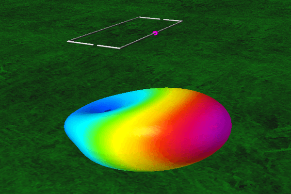
A typical horizontal Moxon with 3D radiation pattern
The Moxon antenna is indeed a good antenna in its own rights but one must remember that it is a structure that has been derived from a standard Yagi. Compared to an equivalent full-sized Yagi, the Moxon is a well thought off compromise. By judiciously bending the elements of a 2-element Yagi at appropriate points along the length of its elements, it forms a physical structure that is easy to build and deploy. A typical Moxon is rectangular in shape.
A Moxon antenna may be deployed either horizontally or vertically. The orientation of the antenna determines its polarization. A horizontal Moxon has horizontal polarization while a vertical Moxon has vertical polarization. A Moxon performs best as a monoband antenna, however, it can also be configured as a multi-band antenna by creating nested Moxon loops. Multi-banding a Moxon is not possible for all bands as some bands detrimentally interact to adversely affect its overall performance. One must also keep in mind that usually, a multi-band Moxon does not produce performance characteristics as good as a mono-band Moxon antenna.
In a nutshell, a Moxon antenna is a good antenna for amateur radio purposes as it offers decent performance. It has a smaller turning radius when rotated. It is structurally robust and easy to construct. Having said that, one must remember that the bent element Yagi design of the Moxon is actually a compromise design. However, the result of this compromise may not always be bad. At the cost of a slight reduction in overall gain, the bent element design produces a broader radiation lobe which could at times be a plus point depending on the application.
Four Square Antenna
The Four Square antenna is actually an antenna array. It is an array of four vertical antennas configured as a driven array where all the four constituent antennas are driven by a transmitter with pre-determined phase shifts. The phase-shifting is done by using proper lengths of transmission lines configured as a phasing harness. In its native form, a Four Square antenna is a mono-band antenna, However, multiband configurations can also be built using a rather complex phasing harness and transmission line switches.
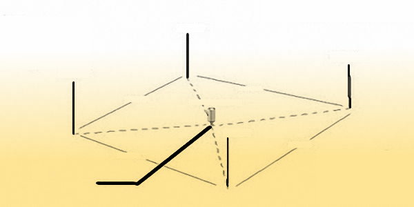
A generic structural layout of a Four Square antenna
A Four Square antenna needs relatively large real estate for deployment. A typical Four Square antenna is mounted on the ground in the form of four properly spaced vertical monopole antennas. However, it may also be deployed at elevated locations like a large roof of a building. For such deployments, this antenna needs an extensive mesh of ground plane radials to perform properly.
The upside of a rooftop deployment on a modern concrete (RCC) building of a Four Square antenna in comparison to many other antennas is that its radiation pattern is not adversely affected by the steel mesh in the concrete roof of the building. In fact, the underlying steel mesh works to our advantage in this case. The adverse effect of steel mesh in the RCC roof of buildings that adversely affect most antennas like dipoles, Yagis, etc is often not well understood by a large section of the amateur radio community. We cover this in detail in a separate article on our website.
We mentioned earlier that despite being a fixed installation antenna the FourSquare antenna radiation lobe can be steered effectively in any direction. This is done electrically and not mechanically. Hence, an antenna rotator is not required.
The azimuth lobe of a Four Square antenna can be switched in four directions that are 90° to one another… At this point, one might say Uh! So, what do I do if I have to work a station between the 90° switched lobes? … Well, don’t fret. This antenna takes care of all situations. The answer lies in the fact that the beamwidth of the lobe is slightly in excess of 90° (±45°). Therefore, the intermediate azimuth angles between any two 90° switched lobes will have low gain ripple which would be perfectly acceptable. In other words, simply by flicking a switch in the ham shack, an operator can orient the main lobe of the antenna in a suitable direction.
One may now ask, how does the antenna work? how is the phasing harness and lobe switcher designed? One can find the answer to all these in our article dedicated to Four Square antennas.
Lazy-H Antenna
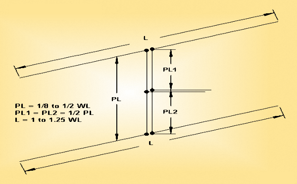
A typical Lazy-H antenna with correct transmission line feed method
Similar to a Doublet antenna, the Lazy-H antenna is a bi-directional antenna. Due to the vertical stacking configuration, the Lazy-H provides elevation lobe compression resulting in additional forward gain and also a lower elevation takeoff angle of radiation. It works well for DX. Being a bi-directional antenna, it provides round-the-world coverage which means that simultaneously receives signals from both the short path (SP) as well as the long path (LP). This may often work to our advantage by constructively enhancing signal strength when both SP and LP openings might be simultaneously available.
The Lazy-H antenna inherits SWR and impedance characteristics from a doublet and hence must be driven using low loss transmission lines like the open-wire TL. Like the doublet, it invariably needs a good wide range antenna tuner (ATU) to be able to effectively load the transmitter and transfer power for radiation. Typically, an additional gain of approximately +3dB over a single Doublet is achievable. Quite often the bandwidth of a Lazy-H is as high as 4:1 spanning over 2 octaves in frequency. For instance, a single Lazy-H antenna covering 40-10m is practical.
Beware of this following mistake when driving a Lazy-H antenna
This brings us to a very important aspect of the Lazy-H antenna as quite often depicted on various websites as well as some books. Many of the configuration diagrams depicting the method of connecting the antenna feeders are wrong. Do a google search for the Lazy-H antenna and you will come across several illustrations showing the two elements connected using a transposed section of transmission line and feeding the antenna at the lower element of the array… This is an absolute blunder.One must remember that one of the best features of a Lazy-H antenna is its broadband capability covering a frequency span as large as 4:1. For this to happen, it is imperative that both the elements of the Lazy-H must always be driven in phase, or else, we will never achieve a broadband constructive interference in the broadside to produce enhanced gain. Many authors miss this simple point. As a consequence, many radio amateurs who construct Lazy-H antennas based on these wrong designs do not get to realize the potential of the Lazy-H.
The length of the transposed section of TL that interconnects the two elements is of fixed length. Hence, it will produce a different amount of phase shift with different frequencies. The narratives of those articles argue that if the spacing of elements is kept at 1/2λ then the 1/2λ transmission line section will produce 180° phase shift and hence transposing it the line at the other end will introduce another 180° shift resulting in in-phase current… True but wrong… It is true because the in-phase condition will only hold at one frequency and therefore the concept will work for one amateur band only. As we change bands, the logic goes for a toss. The phase shift will no more be correct.
What do we have in the above scenario? We have a monoband antenna. So, what’s the point in having a Lazy-H if end up murdering its finest property of allowing multiband (broadband) operation? … How do we set it right? Simple! All that we do is to use non-transposed interconnecting transmission line sections between elements. Then connect the main transmission line feeder from the ATU/Transmitter right in the middle of the interconnecting section. It is as simple as this. Now we will always have a proper in-phase relationship of currents flowing on each of the two elements irrespective of the frequency band. Problem solved.
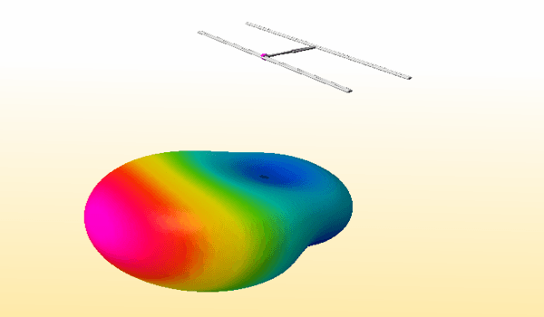
The W8JK Antennas
A typical round-the-world bi-directional W8JK antenna
However, unlike the Lazy-H antenna that we discussed above, it is an end-fire array. Hence, for terrestrial communication purposes, the stacking of the two constituent Doublets is done horizontally. The W8JK antenna looks rather similar to a 2-element Yagi but both the elements of the W8JK antenna are equal in length and closely spaced. Both the doublets are driven elements but unlike the Lazy-H where they were driven in phase, in the case of the W8JK, the two Doublets are driven out of phase with 180° phase difference at the feed-points of the two elements.
Just like the Lazy-H antenna, the W8JK antenna also has broad bandwidth characteristics with of course a large fluctuation of feed-point impedance across the operating frequency span. However, the ensuing range of SWR is tamed by the use of a low loss open-wire transmission line and a good antenna tuner (ATU), similar to the way it is done with the Lazy-H antenna. Typically the bandwidth of a W8JK antenna easily covers a little over 3:1 span. It is quite common for amateur radio installations to deploy a typical W8JK antenna covering 6 amateur radio bands from 20-6m including 17-15-12-10m bands in between. A 20-6m W8JK antenna has about 7.3m long elements and an inter-element spacing of 2.6m thus making it reasonably convenient to deploy and rotate.
The antenna has a bi-directional radiation pattern with excellent lobe patterns, a low elevation takeoff angle, and excellent side-lobe rejection. For best results, a W8JK should be mounted as high above the ground as possible.
Zl Special antenna
This is typically a unidirectional monoband antenna. The ZL Special is a variant of the W8JK antenna. Structurally they are both identical. The only difference is a subtle one involving the feed-point of the array. I will try to highlight this subtle difference that many posts and articles in the webspace usually fail to emphasize.
A ZL Special unidirectional pattern antenna
However, this simple shift in feed-point alters the entire character of the antenna. It turns a ZL special into a unidirectional antenna with increased forward gain. It is no more a round-the-world antenna. Most importantly, unlike the W8JK which is a multi-bander, the ZL Special becomes a mono-band antenna. Having said that, let me mention that a ZL Special multi-band antenna is possible by setting up a switchable transmission line phasing harness that would ensure proper phase shift on each band. The direction of the forward lobe may also be changed from front to back by the phasing harness switch.
What happens? How does it all change so much? How is it done? … We will answer all these questions. ZL Special is a simple variant of W8JK but it produces a remarkable change in characteristics. In the case of a typical W8JK antenna has both the elements are connected to each other using a section of an open-wire transmission line. This TL section is transposed to provide a 180° phase difference between the two. The combined feed to the array is achieved by connecting the main TL to the transmitter at the center of the transposed TL section thus ensuring a proper phase relationship.
To convert the W8JK to a ZL Special, all that we need to do is to shift the common TL feed-point from the center of the transposed TL section towards one side making the lengths of the transposed TL section asymmetrical. This results in an additional phase shift of excitation current flowing on the two elements. As a consequence, the antenna becomes unidirectional by suppressing the original bi-directional lobe on one side while enhancing the lobe on the other side. The net result is to produce an enhanced forward gain in one direction while producing a reasonable front-to-back (F/B) ratio. However, the downside of this arrangement is that the magnitude of the additional phase shift introduced by shifting the common feed-point is frequency-dependent. Hence, unlike the W8JK, the ZL Special becomes a monoband antenna.
The optimum phase shift of current between the two elements of a ZL Special is 135°. Achieving this using a calculated length of the phasing harness of transposed interconnecting TL section is frequency dependant and the approximate 135° phase shift holds true only within a narrow band of frequencies, unlike the required 180° phase shift required for the W8JK. A broadband 180° shift as in the W8JK antenna can simply be achieved by the center-fed transposed transmission line section.
The Hex-beam antenna
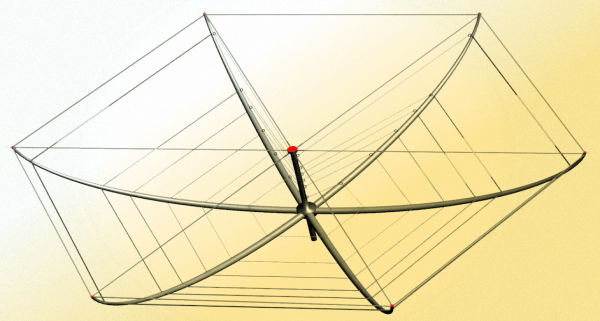
A typical Hex-beam multi-band antenna
Structurally, a Hex-beam antenna consists of six spreaders that are bent into an inverted umbrella shape. These spreaders are typically lightweight fiberglass rods. The advantage of this structure is that it can be used to support multi-band wire elements that successfully maintain a good interelement spacing needed for better performance. A Hex-beam antenna is essentially a derivative of a 2-element Yagi. However, the way in which the elements are geometrically shaped results in sub-optimal overall performance in comparison to a full-blown Yagi. Nevertheless, it is a reasonably acceptable compromise when space is at a premium and a mechanically robust multi-band antenna is desired.
The forward gain of a Hex-beam is typically 1.8-2dB less than that of a full-sized 2-element Yagi. The F/B ratio is rather good if the hex-beam is rather good if it is designed carefully. There is a significant interaction between the elements of the various bands but it can be overcome by carefully tuning the elements. The antenna has a common feed-point and can be fed by a standard coaxial cable to provide acceptable SWR across all bands for which the antenna is designed. The most popular version of a Hex-beam used by radio amateurs on HF bands is a 6 band version covering all bands between 20-6m including various WARC bands. However, we often find some of these larger-sized antennas designed to include the 40m band.
All said and done, a Hex-beam antenna is a fair choice for use on amateur radio bands by operators who space constraints and other limitations.
The Cobweb Antenna
This is a compact multi-band antenna usually designed to cover all bands from 20-6m. It is a lightweight structure with a low wind-loading cross-section making it a robust antenna. Structurally, a Cobweb antenna is relatively small in size yet it offers good overall performance. The Cobweb antenna is typically a fixed mounted antenna that does not require an antenna rotator. It has a nearly omnidirectional radiation pattern in the azimuth.
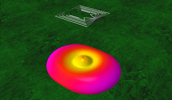
An improved Cobweb multi-band antenna with 3D radiation pattern
The bending of dipole elements into a square shape has several effects on the electrical behavior of the dipoles. Firstly, the open-ends of dipoles are now in close proximity to one another. This has a positive effect of reducing the overall static noise picked up by the antenna and hence a Cobweb antenna is usually a quieter antenna. Secondly, on account of its square element geometry, The radiation pattern of this antenna is no more bi-directional.
The azimuth lobe pattern is nearly omnidirectional. This attribute, of course, results in reduced gain but that should be expected because the gain of any antenna is produced on account of energy concentration in a preferred direction. Since the radiated energy is spread omnidirectionally, the overall gain gets reduced. Another effect of the geometric orientation of elements is to reduce the feed-point impedance of each dipole. This impedance typically drops to 12.5Ω.
The original variant of the Cobweb antenna addressed the low feed-point impedance issue rather cleverly by using an electrical T-match built into every dipole element to elevate the feed-point impedance to the desired 50Ω. These T-matching sections blended so well into the native design that many commentators mistook a Cobweb element to some form of a folded dipole. The dipole elements were created by using closely spaced twin insulated wires (Ex. a speaker wire) that were shorted at the far ends.
However, the most important thing is the way T-match sections were created. The twin-wire dipole elements were symmetrically shorted at specific lengths away from the feed-point thus creating T-match sections. This approach though being a clever concept had a major limitation. It was difficult to replicate unless the same type of twin-wire was to be used. However, the type of twin-wire, their thickness, differences in the dielectric of the insulating material, etc from one installation to another made replication very difficult. The specified design distance of short-circuiting to form the T-match went for a toss. A different shorting point would be needed and hence the feed-point impedance would no more be good enough to produce a low SWR.
The above limitation of the Cobweb antenna design was later circumvented by modified designs that would do away with the T-match arrangement. These new Cobweb antenna designs would use single wire instead of twin-wire as dipole elements. This addressed the replication difficulties but now the feed-point impedance was no more 50Ω, but it was 12.5Ω. Hence, one could no more connect a standard 50Ω transmission line directly. Therefore, the new design used a 1:4 broadband Balun at the antenna feed-point to address the issue. This resulted in the transformation of 12.5Ω to 50Ω by multiplying the impedance magnitude by a factor of four.
Although, the Cobweb antenna does not feature a high gain but it is a quieter multiband omnidirectional antenna with good radiation efficiency. It is a small-sized lightweight antenna and hence can be lofted higher above ground with ease in comparison to other larger structures. To get the most out of a Cobweb antenna and mitigate the effects of lower gain, it is always best to deploy a Cobweb antenna as high above the ground as possible. At a good height above ground, it is a gem of an antenna.
Bobtail Curtain and Bruce Array
These are some of the classic antennas that are quite often used on the lower frequency bands. They fall under the general category of Curtain Array antennas. Basically, these are an array of vertical 1/4λ radiators performing as broadside arrays with bi-directional azimuth lobe patterns. Both the Bobtail curtain as well as the Bruce array are wire antenna structures that cleverly use the antenna wire layout not only to create multiple vertical elements but also serve to provide the required phase shifts to each driven element.
A 4-element Bruce array antenna with 3D radiation pattern
Typically, a Bobtail curtain consists of three vertical radiators with the drive point being on the central element. Several ways of feeding the Bobtail curtain are available but quite often it is driven at the bottom open-end of the central radiator. In this arrangement, it typically requires a counterpoise wire that is laid out along the ground in the plane of the antenna array. As a bi-directional antenna, a Bruce array provides a typical gain in the range of 4-6dBi and is generally used by amateur radio operators for low band DXing.
The Bruce Array is a scalable design using multiple vertical radiators in the array. It is very common to find 4-6 element Bruce array configurations. However, larger arrays with more elements are possible and often deployed. For any particular operating band, the height of the Bruce array remains constant while the width of the array increases proportionately with the increase in the number of elements. Being purely a wire antenna structure, the Bruce array can be easily be deployed even during field operation.
Bruce array may be driven using various different arrangements at different feed-point locations. I have found that the best point to drive a Bruce array is at one of the end vertical elements. The best part about a Bruce array is that impedance matching is a breeze. Simply by shifting the feed-point up or down along the vertical length of a far-end element, one can easily arrive at a good match.
Just like the Bobtail curtain, the Bruce array too is a bi-directional azimuth pattern antenna. It is deployed with the plane of the antenna as vertical to produce clean bi-directional patterns. Interestingly, the radiation pattern of a Bruce array can be tailored to produce a unidirectional pattern by simply tilting the plane of the array away from the vertical. At a tilt of 30-45°, the Bruce array produces a nice and broad forward lobe with a noticeable front-to-back ratio. Consequently, the forward gain of the array also gets enhanced. A tilted Bruce array is often easier to deploy and requires a lower overall height of the fixing points on the upper side. A Bruce array is a great antenna for low band DXing with an inherently low radiation takeoff angle.
We will cover all these miscellaneous antennas and many more in great detail along with their construction designs and performance characteristics under the sub-section of this article in the coming weeks and months.


(21 votes, Rating: 5.00) - Please vote the article with your valuable star rating. Thanks! Basu (VU2NSB)


Ham Rig Reviews Coming Soon
SSN SSNf(10.7) – Real-time Solar Data


