HF Radio Surface Wave propagation (Ground Wave)
Although most of us have an intuitive understanding of the basic concept of surface Wave propagation, many of us often hit against a wall and find it difficult to dig deeper into this subject due to the inherent complexity of this phenomenon. The surface wave (ground wave) propagation is dependent on a variety of physical variables which, at times, makes it confusing for a reader who might not be technically oriented. To address this gap and bring more information and clarity to the readers for understanding the surface wave propagation mode, I will try to keep this narrative simple and support it with a set of illustrative graphs. Let us first identify and list out the major factors that influence surface wave coverage on HF amateur radio bands.
Factors influencing Surface Wave Propagation behavior
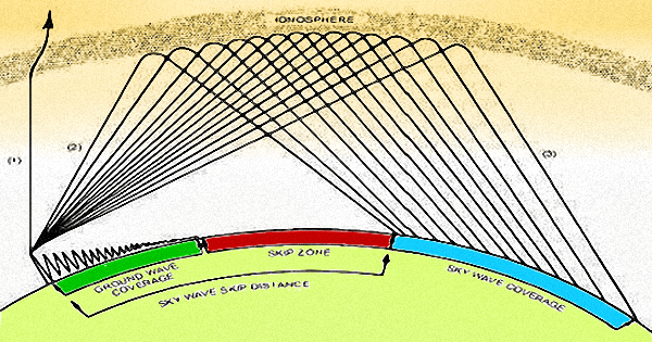
The illustration depicts the region around the transmitter location that is covered by the Surface Wave (Ground Wave) propagation mode. This could typically fill a large portion of the Skip-distance that is produced on account of Ionospheric propagation. On the lower frequency HF bands, progressively the Skip-Zone (deaf zone) that lies between the skip distance and the surface wave coverage gradually diminishes to eventually merge. This could prevent a deaf zone on lower frequency HF bands especially during medium SSN conditions. The Surface wave coverage region is shown by the Green arc, while the Ionospheric skip coverage is shown by the Cyan arc. The balance distance in Red represents the zero coverage Skip-Zone.
The most important property of Ground wave propagation is that it propagates parallel to the surface of the earth. It makes the attenuation strongly dependent on the terrain constants (conductivity and permittivity), as well as other factors like polarization, antenna height, distance, and frequency. Over non-homogeneous paths, the use of vertical polarization is the only practical way of leveraging this propagation mode, because the ground quickly absorbs horizontal polarization. Even vertical polarization suffers high attenuation if the ground (soil) conductivity is poor. Paths over the sea or oceans have lesser propagation losses because of the increased conductivity of the seawater.
The surface wave propagation depends on currents that flow in the ground. The existence of the atmosphere changes the propagation characteristics but is not essential for the mode. Horizontally polarized surface waves are very heavily attenuated and have little or no practical worth. All the discussion that follows would be based on vertically polarized surface waves.
Ground Conductivity – Factors influencing conductivity include moisture content and temperature. Besides, it is necessary to consider the general geological structure of the soil, the topology of the path, as well as loss due to absorption by surface objects.
Terrain Irregularities – Shadowing which may occur in certain locations as a result of terrain and terrain irregularities may result in attenuation and phase differences for received signals. The effect on the field strength produced by terrain irregularities varies with the frequency of transmission and the specific characteristics of the irregularity. Mountainous terrain may increase signal strength through knife-edge diffraction, a phenomenon known as obstacle gain. Although it is a part of the surface wave (ground wave), diffraction is not covered in this article. To learn more about the RF diffraction phenomena, please read my article titled Terrestrial VHF Radio Signal Coverage – BLOS where I have covered this subject in fair detail.
Vegetation – Vegetation along the propagation path also influences field strength. For instance, a densely forested area will produce different propagation results than one with no vegetation, and the effect will depend on whether the forest is in leaf, wet, or covered in snow. However, below about 2 MHz, a forest environment has little effect on the ground wave.
Surface Clutter – Buildings, urban areas, steel framing, wiring, plumbing, lamp posts, and other surface objects affect propagation, and are collectively known as surface clutter.
A highlight of HF surface wave is that it is uniquely suited to situations arising out of disaster or other emergency conditions. The surface wave (ground wave) communication offers a nuclear survivable method of communication in tactical environments. Surface wave does not rely on the ionosphere for the propagation of the signal, and therefore is not susceptible to ionospheric conditions resulting from EMP produced by a nuclear explosion.
Surface wave (Ground wave) Propagation on amateur Radio HF Bands
Let us now take a look at some of the aspects of surface Wave propagation as it manifests itself on amateur radio HF bands. I will present below a set of attenuation curves representing typical behavior on all ten bands including 160-80-60-40-30-20-17-15-12-10m.
Although it should be self-explanatory, I will also explain how to interpret the attenuation graphs for those who might find them a bit confusing. Moreover, I will also draw attention to some of the other factors that one might tend to ignore at first glance.
For the sake of this presentation, let me cite below the conditions for which the surface wave propagation graphs are applicable. These attenuation curves have been derived from a simplified but fairly accurate model based on the CCIR ITU-R P_368-7 1992 recommendations for evaluating ground wave propagation over a smooth surface spherical earth. However, my model has been simplified to account for Sommerfeld-Norton Planar Earth theory since the curvature of the earth can be reasonably approximated due to the relatively short surface distances involved. The model complies to ±3 dB accuracy of the results mapped by the ITU 368-7 document.
Rather than using a long drawn set of complex equations involving tons of variables, I have derived various intermediate constants applicable to each amateur radio band in question under the specific set of conditions under consideration. This takes into account both the Sommerfeld region that defines the radio horizon as well as the Diffraction region that extends beyond the radio horizon. A normal good quality ground with Soil Conductivity of 8 mS/m and Dielectric Constant of 15 have been assumed as the basic terrain parameters. The overhead Tropospheric Diffraction Factor has been set to 0.958 to arrive at the computations.
Although the set of attenuation curves presented below have been computed taking average global terrain and atmospheric conditions into account, it may well be possible that for some regions with extreme deviations in the terrain properties or under extreme weather conditions, these attenuation figures may not remain true. There could be some deviation from the results projects below. However, with due diligence and application of mind, one should be able to apply acceptable correction on account of the altered situations. I will explain some of these points later.
Important points to remember are that the following attenuation projections have been made under the terrain and tropospheric conditions cited above and also assuming that there is no ionospheric skywave available. All curves given below have be derived assuming vertical polarization only. The attenuation on account of horizontal polarization is usually unacceptably high under most circumstances, thus rendering such a communication circuit practically useless. Therefore, I have made no attempts to perform computations for horizontal polarization. The antennas at both ends are assumed to be at or near ground level. The following results conform closely to what might be computed by ITU-R GRWAVE.
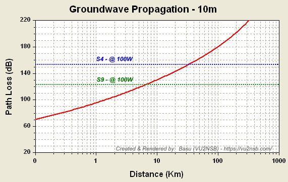
10m HF band Surface Wave (Ground Wave) coverage under typical terrain conditions as stated in the article.

12m HF band Surface Wave (Ground Wave) coverage under typical terrain conditions as stated in the article.
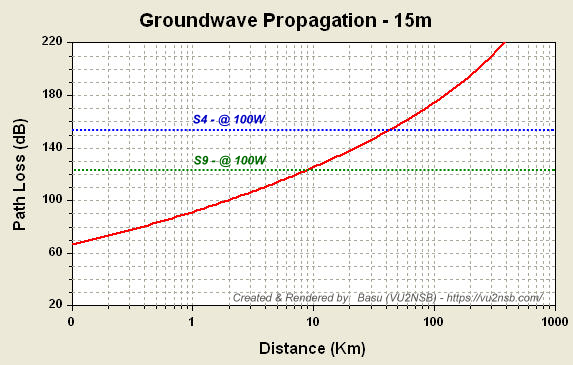
15m HF band Surface Wave (Ground Wave) coverage under typical terrain conditions as stated in the article.
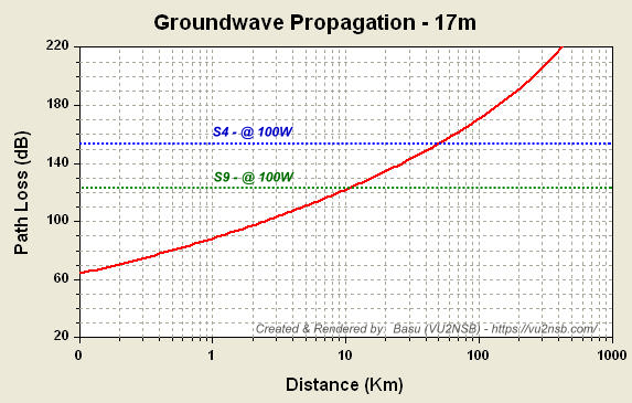
17m HF band Surface Wave (Ground Wave) coverage under typical terrain conditions as stated in the article.

20m HF band Surface Wave (Ground Wave) coverage under typical terrain conditions as stated in the article.
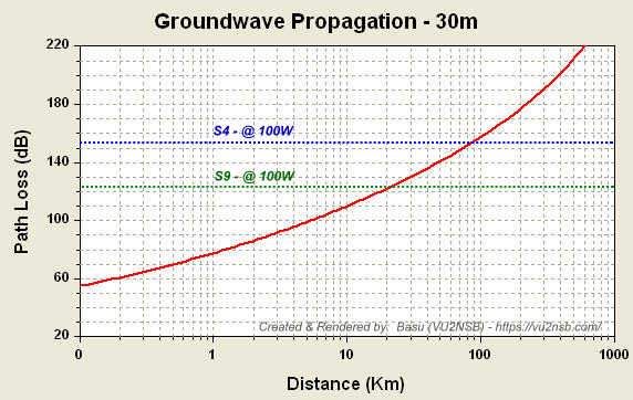
30m HF band Surface Wave (Ground Wave) coverage under typical terrain conditions as stated in the article.
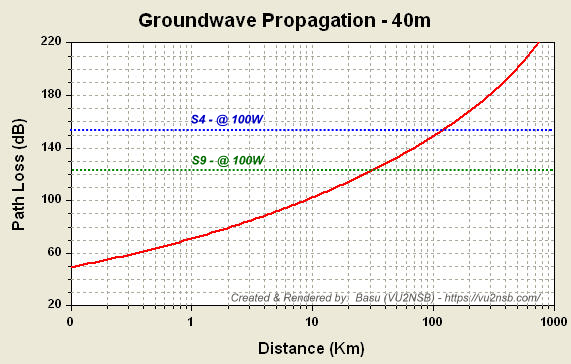
40m HF band Surface Wave (Ground Wave) coverage under typical terrain conditions as stated in the article.

60m HF band Surface Wave (Ground Wave) coverage under typical terrain conditions as stated in the article.
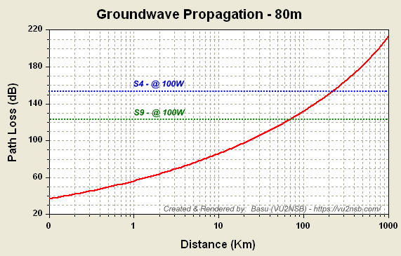
80m HF band Surface Wave (Ground Wave) coverage under typical terrain conditions as stated in the article.
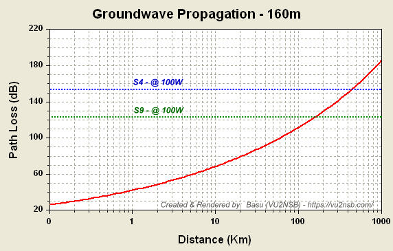
160m HF band Surface Wave (Ground Wave) coverage under typical terrain conditions as stated in the article.
Please keep in mind that the night-time range coverage might increase in event of additional surface dew formation, ionospheric reflected component, or increase in tropospheric refractivity gradient. There could be seasonal variations in coverage range too especially after widespread rain.
In some cases, there may be seasonal variations in surface wave propagation. These may be attributed to changes in the refractivity of the troposphere, to the state of vegetative cover, to changes in the level of the water table within the ground, to freezing conditions where water becomes ice, or to a thick snow-cover, etc., where these may cause changes in the effective ground conductivity. All of these changes may affect the intensity of the surface wave field. In particular, such seasonal changes may result in a reduction in field strength in summer.
The attenuation of the surface wave propagating signals from rural transmitters into densely built-up urban areas in the courtyard of high buildings may result in a sharp decrease of the level of a signal by an excess of 15-20 dB over the nominal value projected by the attenuation curves.
Another point to be remembered is that we have not accounted for the additional attenuation that might exist on account of the non-homogeneous surface wave propagation path. In such cases, the Millington method for computing the ground-wave amplitude over non-homogeneous paths needs to be done. However, this does not imply that our simplified model is inaccurate under typical conditions because excessive non-homogeneity usually does not exist over shorter distances as in the case of HF Surface wave (Ground wave) propagation. This would have been an important factor if we had been calculating for longer distances as in the case of low MF, LF, VLF bands, etc. This is because the Surface wave coverage range would have been very long where terrain non-homogeneity would be a prominent factor.
Here are some of the salient points that should be kept in mind while drawing inferences from the set of signal attenuation curves that I provided above. I will try to draw these inferences in conjunction with some of the important practical aspects and limitations of typical amateur radio station installations.
- Antenna Polarization - Quite often while dealing with ground wave coverage range, amateur radio operators tend to neglect the fact that most of the talk about extended short/medium range coverage by this mode, especially on the top bands is practically applicable only in the case of vertically polarized radio waves. In the case of horizontal polarization, we would rarely have any worthwhile coverage due to the short-circuiting of the parallelly oriented E-field of the propagating wave, resulting in rapid dissipation of signal energy into the earth... Remember, all MF (MW) AM broadcast stations intended for local regional coverage use vertical antennas and not dipoles or other horizontally polarized antennas. Their objective has always been to leverage the surface wave propagation phenomena to the maximum.
- The Polarization Dilemma - Typical amateur radio antennas, especially on the lower frequency bands where surface wave propagation is more relevant are mostly horizontally polarized. The antennas like the dipole, inverted-V, long-wire, Windom, OCFD, G5RV, horizontal loops, etc., are all predominantly horizontally polarized. Although the vertical 1/4 λ antenna, or any of its shortened version has vertical polarization, we don't see them being used by radio amateurs so often on the top bands. This is because they come with their baggage of issues like lower gain, lower bandwidth (in the case of shortened version), and certainly on account of accentuated noise (QRM) pickup by this type of antenna. Whatever might be the reason, it is the horizontal polarization that is more popular thus making the surface wave propagation practically unavailable... However, some wire antennas like the Bobtail curtain, Bruce Array, etc., are fairly easy to set up and operate. They feature vertical polarization and also have substantial gain with a bi-directional radiation pattern in the azimuth.
- Cross-Polarization Issues - Unlike MW AM broadcast stations, amateur radio communication has to deal with another issue related to surface wave (ground wave) signal polarization. Being a two-way radio communication system, the stations at both ends must be able to read one another. Therefore, for this to happen over ground wave propagation, both stations would need to have vertically polarized antennas... Unfortunately, this condition might rarely be met... What happens if the two stations have different antenna polarization? Well! The first thing is there would be an additional cross-polarization loss to the tune of 20-30 dB that would come into play. Though this would reduce the coverage range substantially, yet it may not be the deal-breaker. The bigger problem is that although the station transmitting with vertical polarization might be heard by the other station with horizontal polarization (despite the additional cross-polarization loss), the other station, when it transmits back will not be copied by the first station because its signal will be horizontally polarized and it will run into the ground and disappear rapidly due to the greater attenuation and absorption by the ground.
- Antenna Height for Surface Wave Communication - for surface wave (ground wave) propagation-based communication to be viable it is important that both the TX and RX antennas are installed at the ground level or at least within a 1/4 λ from the earth's surface for best results. The surface wave propagation occurs by ensuring that the signal clings to the surface of the earth. Hence, it is not available at heights that are well above the ground.
- Surface Wave Range Coverage - The graphs are shown above with attenuation curves for each HF band as a function of distance, also have dotted horizontal line markers, in blue and green. They represent the equivalent signal strengths on account of attenuation at the receiver in S-Units for two levels, S4 and S9... These signal strengths are expected at the RX end when the transmitter power is 100W. In the case of higher or lower TX power, these horizontal dotted marker lines will shift higher or lower on the graph by the number of dB of TX power change from the reference of 100W. The expected surface wave coverage distance on each band to attain the S4 and S9 signals may now easily be read on the horizontal scale at the intersection points of the red curve and the dotted marker lines.
- Influence of Noise on Range coverage - It is a known fact that the lower the frequency band on HF, the greater is the magnitude of aggregate RF noise. This effect is aggravated further due to the vertical polarization that we need for meaningful and viable surface wave propagation to exist. Therefore, although on 10m-12m-15m-17m, and perhaps even on 20m, the distance coverage designated at S4 received signal level could be possible due to lower aggregate noise level, it might not be possible between 40-160m bands. As the noise-floor levels increase on the lower bands, it may be as high as S5-S6 at geographic locations despite excellent antenna and station setup. Therefore, after allowing for a reasonable SNR margin, signals below the S7 level might not be readable at such locations on the lower frequency HF bands... Not to mention the stations with carelessly set up antenna systems, where it might not be a surprise to see a noise floor of S9 or even higher on the radio receiver. Under most circumstances, such a poor noise performance of the antenna system is quite avoidable if more informed thought were to go into improving the antenna system setup. Check-out my articles on this subject titled Understanding Antennas – The Good, the Bad, and the Ugly... The bottom line is that the worse your antenna is in terms of extraneous noise pickup, the poorer will be your prospects working reasonable distance on top bands using the surface wave propagation mode. In many cases, due to (avoidable) noise limitations, the surface wave range coverage could get restricted to distances far less than what is depicted by the S9 dotted marker line.
- Variations due to Terrain Parameters - Finally before I wind up this article, let me once again draw your attention to the fact that all calculations and projections have been made while taking into account average soil quality as one might expect at a typical geographic location. This is based on Soil Conductivity of 8 mS/m and a Dielectric Constant of 15. However, when there are drastic variations in these parameters, especially the conductivity, then the attenuation values shown in the graphs would also change. For instance, in the case of surface wave propagation over water, or even more conductive saline seawater, the surface wave coverage range might increase greatly, at times it could be an order of magnitude higher. Then again, this too could vary significantly depending on the choppiness of the sea. When the sea (ocean) water is tranquil, very few low amplitude waves are present, then the surface wave coverage extends over a longer range. On the other hand, in the case of a turbulent sea with water surface unevenness and roughness, the surface wave range decreases. Similarly, on dry, rocky, or desert land too, the coverage range might get significantly restricted... Moreover, the atmospheric conditions also play a notable role at times, when the vertical Tropospheric refractive gradient becomes large.
 1")

(15 votes, Rating: 5.00) - Please vote the article with your valuable star rating. Thanks! Basu (VU2NSB)


SSN SSNf(10.7) – Real-time Solar Data