

HF Wire Antennas – A Primer
Most wire antennas are horizontally polarized due to their physical orientation. Although the surface wave (ground wave) range of these antennas is lower than the vertically polarized ones on account of horizontal linear polarization, the fact of the matter is that they leverage the properties of the ground (earth’s surface) underneath to provide excellent performance characteristics which are suitable for sky-wave ionospheric skip mode long distance (DX) propagation on HF radio bands. Essentially, these antennas may be classified in two distinct types; the standing-wave and the traveling-wave antennas.
Standing-wave Mono-band Resonant Wire Antennas

Dipole – A resonant mono-band antenna
As stated earlier, the typical horizontally polarized HF wire antennas leverage additional gain on account of the proximity w.r.t the earth surface in comparison to their free-space gain. The ground beneath the antenna acts as a reflector. A direct radiation ray from the antennas at any elevation angle is met with another parallel ray which is created by ground reflection. The phase difference between these two rays will vary depending on their path lengths. At certain radiation angles, these two rays (direct and ground reflected) are in phase and they constructively interfere to produce enhanced strength at that angle, whereas, there are other angles where these two rays may be 180° out of phase and hence the cancel each other.

Azimuth radiation lobe pattern of a dipole
The quality of the soil composition and moisture determines the quality of the ground. How good or how poor the reflection properties of the ground are at any particular antenna deployment location is determined by the soil conductivity and its dielectric constant. The greater the conductivity and the dielectric constant, the lesser is the ground absorption loss and better is the reflection efficiency. Hence, a radio station with its antenna located in a dry, sandy, desert location will not be able to leverage the advantage of ground reflection so well as a station antenna located above a fertile, moist or marshy land. The best and least lossy reflections will occur at sea-coast or near large lakes and water bodies. Similarly, a maritime mobile ship-based HF station using a wire antenna has a great advantage provided by the surrounding seawater.
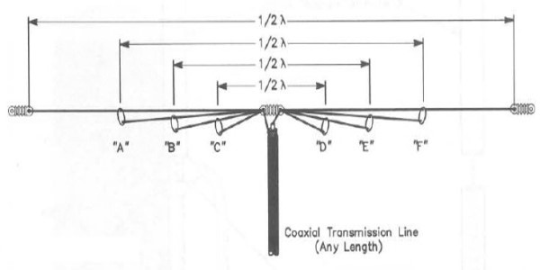
Additionally, several designs of horizontal Collinear wire antennas of various types are also available which combine several axially extended 1/2λ sections combined using phasing methods to produce much higher gain with narrower azimuth beamwidth. These antennas are center-fed like a dipole.
Standing-wave Multi-band Resonant Wire Antennas
Multi-band resonant Fan Dipole antenna
The second method that would work for any dual-band (two bands) combination is to use two orthogonal dipoles (oriented at 90° w.r.t to each other) and feeding them both at the central point using a single transmission line connecting both antennas in parallel. The problem with this approach is that the direction of radiation of the constituent dipoles will have a 90° offset on the azimuth and hence the peak radiation on each band will be in different directions. Unless that is not a problem or if the objective is to work short distances with Near Vertical Incidence Skywave (NVIS) by mounting the antenna close to the ground, this method would usually be unsuitable. This approach would work for NVIS because the antenna will produce an omnidirectional pattern.
Till WARC bands came into being, all amateur HF bands were harmonically related. Traditionally, we had 160-80-40-20-15-10m bands available for HF amateur radio service. Barring the 15m band, the rest of them all have an octave (x2) relationship with the next adjacent band. They have a direct harmonic frequency relationship with the next adjacent band. Although 15m which lies between 20m and 10m does not have a harmonic relationship with one another, 15m is the third harmonic of the 40m band.
That is the saving grace which helps antenna designers to often include the 15m too in a multi-band antenna design but not always. However, making a multi-band resonant wire antenna for covering all other bands minus 15m is quite trivial thanks to the nature of amateur radio band allocation. Later, when WARC bands 60-30-17-12m bands were opened for amateur service, it created a headache for antenna designers to incorporate these non-harmonically related bands in their multi-band wire antenna designs.

G5RV – Azimuth lobe pattern on 20m
Other ones, the G5RV, Windom, OCFD, and W3EDP are designed to have a certain specific length which allows a complex harmonic relationship between the multiple bands they cater to. The design length of these antennas needs to be faithfully replicated for them to function properly. Quite often, these antennas cover 4-5 amateur radio bands. On most of these bands, these antennas feature a fairly acceptable SWR and therefore can easily be connected to the transmitter without any external antenna matching unit (ATU). However, an ATU may be required for some other bands to be able to work effectively.
Barring the Trap dipole, Fan Dipole, and the Open Sleeve Dipole which produce bidirectional radiation patterns almost similar to a standard dipole, the other ones like the G5RV, OCFD, W3EDP, Windom, etc produce azimuth radiation patterns that are dependant on the frequency band of operation. Most often on the lower frequency bands, they all produce a well known bidirectional pattern. However, as we progressively switch to the higher frequency bands, the azimuth radiation lobes split up and tend to gradually swing towards the axis of the wire. This effect is more pronounced as we go higher in frequency. On some high-frequency bands, the optimum direction radiation could swing as much as 40-50° away from the broad-side direction of the antenna wire.
They may also produce a fairly deep null in the broad-side direction on these higher frequency bands. Overall, these antennas produce quite a good gain especially on the higher frequency bands at reasonably low take-off angles to ensure great prospects for working HF DX. Tens of thousands of HF DX operators around the world have used these antennas with great success for many decades and they would all swear by the performance of these light-weight and unobtrusive multi-band wire antennas.
Traveling-wave Broadband Wire Antennas
The traveling-wave wire antennas, on the other hand, are non-resonant antennas. There feature broadband characteristics and are typically usable across one or more frequency octave (2x or more bandwidth). The length of these wire antennas is not critical, however, the lowest frequency of operation is limited by the length of the wire. These wire antennas are usually terminated by a load resistance at the far-end which may be either terminated to ground or else to a symmetric return wire.

A typical traveling-wave Rhombic antenna
Another important of this type of wire antenna which usually manifests itself for multi-wavelength type configurations is that they may be deployed in close proximity (2-3 meter) above ground, yet they would produce low-angle radiation lobes (in the elevation plane) making them perfect for long-skip ionospheric communication for DX work. Due to very long wire lengths normally required for these antennas, they are not practical where the available physical space is limited. another downside is that due to their sheer length, they are typically fixed antennas which can neither be easily be re-oriented after installation nor can they be physically redeployed at short notice. Hence, though most of these traveling-wave wire antennas are perfect for point-to-point HF communication, they are not so practical general-purpose antennas for typical amateur radio work.
An interesting feature of traveling-wave wire antennas which are terminated with a load resistor, as we noted earlier results in some dissipation loss in the terminating load. On account of this, the forward transmit power gain is lower than what might have been otherwise. Therefore, a practical antenna of this type will have higher gain in receive mode due to Receive Directivity Factor (RDF) than the forward power gain in transmit mode. This has led to a myth, especially amongst a large section of amateur radio operators that these antennas are receive-only antennas and not suitable as transmitting antennas. Nothing can be farther from the truth. One must realize, that some of the other popular antennas which are commonly used by amateur radio operators too have a differential between the RDF gain and power gain. Though it is true that the differential is more pronounced in the case of these antennas.
Unlike multi-band resonant wire antennas, the traveling wave antennas have a uniformly directed radiation pattern which does not change drastically with the frequency band of operation. In other words, the direction of the radiating lobes of traveling-wave antennas remains more-or-less same irrespective of the operating band, whereas, in the case of multi-band resonant wire antennas, the direction of azimuth orientation of the main lobe may differ from band to band.
Some of the well-known traveling-wave wire antennas are the Rhombic and the Beverage. Another class of antennas which too are traveling-wave antennas but rarely recognized as such are the T2FD and T3FD antennas. Unlike the first two cited examples, these antennas physically resemble a folded dipole antenna due to a similar-looking structure and therefore named that way. However, they actually do not create standing waves but they produce traveling waves that terminate into a dissipative load.
Other Non-resonant Wire Antennas
Amateur radio operators are at times quite innovative when it comes to antennas. Very often due to physical space constraints or other reasons, we find that hams try to deploy various configurations of random length wires and try to make them work as their station antenna. Most of the time, these random-lengths, randomly oriented wires driven at unconventional feed-point locations eventually end up allowing them to make a few radio contacts here and there. However, such random type antennas are never efficient and only work when the propagation conditions are really good. What is common about such innovative endeavors is that they all invariably need a good ATU to tune and transmit on the frequency of interest. They are usually non-resonant antennas and needless to say have dubious performance. However, as the saying goes, when the propagation conditions are good, then even a coat hanger might be made to work as an antenna to establish radio contact.

Double Zepp (Doublet) antenna geometry.
Fine examples of great non-resonant antennas are the Zepplin, Double Zepplin or the Doublet antenna. A Doublet antenna is often used very effectively as a multi-band HF antenna by many amateur radio operators. It consists of a dipole like geometric structure but the wire length is not resonant on practically any of the operating bands. It requires a certain length of open-wire transmission line connected to the feed-point of the antenna. The length of the Doublet antenna elements and the length of the required open-wire line segment has a mathematical correlation. Certain specific combinations of these lengths perform optimally as a multi-band antenna. The performance of a Doublet is rather good and it produces a good bidirectional azimuth lobe pattern on all bands. However, as we mentioned before, it needs a good ATU to work.
Another modestly good non-resonant multi-band wire antenna is what is called a Long Wire antenna. It may be geometrically oriented like a dipole or a V-antenna. A long wire antenna may be center-fed or off-center fed. When we speak of Long wire antennas, many people believe that any length of wire as long it is fairly long in length will do. This is not entirely true. Although one can choose from a large selection of acceptable lengths of wire for this antenna, any random length unless it happens to be one of the preferred lengths will most often land the operator in trouble. Some lengths are absolutely not acceptable as they would reflect high impedance voltage nodes at the feed-point thus rendering very high SWR. Since most of our amateur radio bands are harmonically related, such a scenario will cause havoc on most bands.
However, the good thing is that increasing or decreasing the length by just a meter or two will usually resolve the problem on all bands. It does not mean that a Long Wire antenna length can only be determined by trial and error. On the contrary, very precise calculations can be made beforehand and several acceptable lengths can be suggested prior to installation. There is indeed a method to the madness. The azimuth lobe directions of this antenna will vary from band-to-band and it too will require an ATU to function effectively.
The subject of wire antennas is so vast that we can go on endlessly citing different designs and their performance. However, we have tried to touch upon most of the popular wire antennas in this article. We will dwell deep into the design and performance of many of these antennas in separate dedicated articles over a period of time.
List of Articles under this Section
- The Center-fed Half-Wave Resonant Dipole Antenna The Dipole antenna is perhaps structurally the simplest antenna to fabricate and deploy. It requires a minimal set of hardware components and is quite light-weight. All Dipole antennas...
- The Center-fed Half-Wave Dipole Inverted V Antenna An Inverted V antenna is a very popular variant of the standard horizontal dipole. In his article, I will try to bust some of the myths associated with Inverted V and dipoles....
- Multiband End-Fed Half-Wave EFHW Antenna The End Fed Half Wave antenna or the popularly known EFHW antenna has been around almost ever since the inception of HF radio. Nevertheless, the EFHW antenna had in the past, been rather...


(30 votes, Rating: 5.00) - Please vote the article with your valuable star rating. Thanks! Basu (VU2NSB)


Ham Rig Reviews Coming Soon
SSN SSNf(10.7) – Real-time Solar Data


