

Does antenna height matter more than gain?
Does this mean that we need to search for some special kind of antenna with low TOA capability to deploy at our QTH? NO! We don’t… Every antenna can be installed in a manner so as to provide low TOA, however, the user must be aware of how it could be done. The general problem across a large section of the radio amateur community is the lack of sufficient appreciation of how a simple additional increase in antenna height could allow us to begin to copy those stations that we never knew even existed. Ironically, we usually don’t do much to carry out simple tweaks that could redress this salvageable situation. Instead, our first reaction is to figure out how to replace our existing antenna with another larger, heavier, and higher-gain antenna… Many of us often blindly walk down this apparently lucrative and rosy path to eventually end up scratching our heads when the results turn out contrary to our great expectations.
Here is a real-world question from a fellow amateur radio operator. This pertains to the fact that low takeoff angle radiations from antennas installed high above ground may often produce far stronger signals compared to another better and a higher gain antenna installed at a lower height AGL.
Our friend in the Facebook post cited a scenario where although he has a perfectly working Fan Dipole at 55 feet AGL chooses to install an additional higher-gain directional antenna, the Hex-Beam to further enhance his station performance. However, the final Hex-Beam installation on a tower, rotator, and mast had to be put up at a height of 29 feet AGL. It is understandable… Most of us as radio amateurs often face various constraints including city laws, housing society bye-laws, cost, etc that prevent us from installing very tall towers to mount our antennas. On the other hand, simple, light-weight wire antennas like dipoles, etc may be easier to install at greater heights by using pre-existing artifacts on buildings, other structures, trees, etc as end-point anchors for the wire antennas. At times, we do not even need to build additional infrastructure for deploying wire antennas. As a consequence, it is usually far easier for most of us to put up simple wire antennas at much greater heights than Yagis, cubical Quads, Hex-Beams, Moxons, LPDA, or whatever.
The above factor usually gives us the leverage that many of us fail to recognize. I am not suggesting that larger high-gain antennas do not have much to offer us. In fact, they do provide us with amazing and highly enhanced performance opportunities but only when deployed properly in a way that allows their performance parameters to manifest themselves. Ironically, most of the amateur radio operators, on account of various legal, real-estate, and logistic constraints often find themselves in a quagmire that prevents the larger antenna from blooming into its full potential.
One must remember that a simple wire antenna operating under conditions of optimal deployment might perform far better than a bigger higher gain antenna deployed under compromised installation environment.
Antenna Gain vs Radiation Takeoff angle (TOA) – Their significance
The power gain of an antenna is generally specified by the designer or the manufacturer. This is typically measured in either dBi or dBd. Those who want to know more about these gain units might like to refer to the article on Antenna Fundamentals. Whatever be the units of gain specification, the figure specified in a manufacturers datasheet indicates how much gain to expect under a set of specified conditions as laid down by the manufacturer in the datasheet.
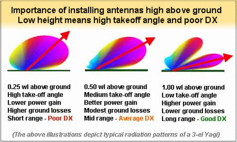
Comparison of radiation takeoff angle for maximum gain for an antenna installed a various different heights above ground level. As a consequence, the elevation section lobe pattern differs offering different long-range DX performance.
Hence, for instance, if we want to achieve a reasonably good gain at 10° TOA, then it will be far better if our antenna were to achieve its maximum specified gain at say 20° TOA rather than it at say 35° TOA. The peak (maximum) gain TOA of either 20° or 35° will be determined entirely by the effective antenna height of the antenna above ground level. The higher the antenna above ground, the lower will be the primary lobe’s peak TOA. In other words, the same antenna could provide us with 20° TOA peak gain instead of 35° TOA peak when deployed at a greater height.
Therefore, with an antenna installation at a greater height, since the peak gain TOA is closer to our desired operational TOA requirement of 10°, the reduction in gain at our desired 10° TOA w.r.t the datasheet specified gain will be less in comparison to the reduction expected when the peak gain is at 35° TOA.
Some of us might initially find the above explanation slightly confusing. In that case, I would request you to read it over again in conjunction with the associated illustration that not only shows elevation section lobe patterns at various antenna heights above ground but also shows the maximum (peak) gain TOA for each case. I hope it will help in understanding the concept.
In the associated illustration one might also notice that I have specified all antenna heights in terms of wavelength (λ) or a fraction thereof, instead of using absolute units of measurement like meters, feet, etc. This is a deliberate choice. While designing, characterizing, or evaluating antennas we prefer to use λ as the unit of length or distance. This allows us to specify antenna performance more-or-less universally without worrying about the frequency of operation.
For instance, an antenna installed at 1/2λ height above ground (20m AGL) on 40m band will produce a similar radiation pattern if a 10m antenna were to be installed at 1/2λ above ground (5m AGL) in accordance to its wavelength. Therefore a constant wavelength above ground determines the similarity in performance. On the other hand, a constant antenna height AGL in terms of meter or feet will not maintain the similarity of performance on different bands. A 40m band antenna at 20m AGL will have very different performance and radion lobe patterns in comparison to a 10m band antenna at the same 20m AGL.
The illustration also shows quite clearly how the same antenna installed at various heights above ground level would produce quite differently shaped radiation pattern in the elevation plane thus making the primary radiation lobe either more upwards or closer to the horizontal. As a consequence, the angle of maximum (peak) gain of the lobe also changes thus resulting in large gain variations at lower takeoff angles (TOA) and hence also its DX performance.
How the Antenna Height AGL might overshadow Higher Gain
Now, let us try to address the specific question that formed the basis of this post. Why at times, might antenna height matter more than gain? Why did the Hex-Beam antenna of our friend not perform as well as his Fan-dipole? So, here I present a fairly similar scenario along with analysis based on mathematical modeling.
In our example, I have also used a dipole at 55 feet AGL but instead of the Hex-Beam, I modeled a 3-element Yagi which actually has a higher gain than the hex-beam. To compensate for the additional gain of the Yagi, I placed it at 25 feet AGL. Therefore our conditions of comparison are pretty similar to the practical situation of our friend. Although the frequency band was not originally specified, I carried out a performance evaluation on the 20m band which I believe might be the most probable and fair assumption. Moreover, even if the operating band in the original case might have been either 40m or 15m, the relative behavioral trend between the antennas would be fairly similar.
Here is what we observe… Check it out…
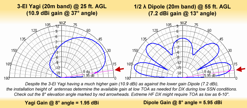
A usable antenna gain at low radiation takeoff angles (TOA) is essential for reliable DX range HF operation especially during low SSN conditions. This illustration depicts the unquestionable importance of installing the antenna a good height above ground to ensure optimum low TOA performance.
The 3-el Yagi in question has a typical maximum gain of around 11 dBi while the dipole has a maximum gain of about 7-7.5 dBi. These are realistic performance figures as one might expect for practical antennas. The gain of both the Yagi as well as the dipole will vary marginally on account of installation height.
In our case, when installed at 25 feet AGL, the Yagi provided a maximum forward gain of 10.9 dBi, while the dipole at 55 feet AGL produces a peak gain of 7.2 dBi... Therefore, if we take the antenna gains as the yardstick of evaluation, then the Yagi installation provides us 10.9 - 7.2 = 3.7 dBi higher gain than our dipole installation. One might prima-facie conclude that the Yagi outperforms the dipole by a significant margin.
However, is the above conclusion really true? Although for short and medium range communication it might be true during moderate and high SSN conditions, in the case of DX, especially under the present conditions of low SSN due to bottom ebb between the Solar Cycles 24th and 25th, the above conclusion is lobsided and totally untrue.
During low SSN conditions, due to the low plasma density of the ionosphere and reduced ionospheric slab thickness, the higher angle radiations tend to penetrate the ionosphere while most of the long skip DX activity occurs at antenna TOA that is much lower than usual. The optimum DX radio circuit performance on many HF bands might happen with antenna radiations being received and transmitted at angles as low as 6°-10° w.r.t to the horizontal ground.
The above explanations bring us to another vital point that is rarely appreciated among the majority of radio amateurs... When people say that HF bands are dead due to low SSN and low solar activity, it is not entirely true. The bands are not dead. They have shifted their optimum angle of skip to a very low angle. Most amateur radio antennas begin to fail because they are inadequate to perform at these low TOA. Instead of blaming our antenna inadequacies (that can be set right), we find it more convenient to pass the buck to the propagation conditions and pin the blame on low SSN. The examples of antennas at a different height that we are discussing here will perhaps throw some light on what I am attempting to imply.
Now, let us return our focus to the above illustration and our comparison between the Yagi and the Dipole at different heights. Although the Yagi has a 3.7 dBi higher maximum gain than the dipole, let us see what happens at the desired TOA between 6° and 10° where all the low SSN DX action lies. We will compare the gains of both these antennas at 8° TOA.
The Yagi at 25 feet AGL yields a gain of 1.95 dBi as seen in the illustration. Although the peak gain was 10.9 dBi at 37° angle, it reduces drastically at 8°. On the other hand, the Dipole at 55 feet AGL, surprisingly, yields a gain of 5.95 dBi. This amounts to the dipole producing 4 dB higher gain than the Yagi, even though the peak gain of this dipole at 13° peaked only to 7.2 dBi (3.7 dB less than the Yagi). Why did the Dipole beat the Yagi hollow at 8° TOA? This is because the Dipole was much higher AGL in comparison to the Yagi. Even though the Yagi has a higher peak forward gain, it failed to produce enough gain at low TOA.
To conclude in a nutshell, never underestimate the power of antenna height AGL. No point in investing in large and heavy higher gain antennas unless you can hoist it high enough to beat a lighter weight but lower gain wire antenna that might already be deployed at a good height. Also, keep in mind that the antenna height above ground level does not always mean the height of the antenna above the soil ground. This is true especially in urban areas with concrete structures and buildings. One might be tempted to install the antenna on top of a tall multistorey building to end up blissfully unaware that the effective antenna height does not actually include the building height. To learn more about this lesser-known aspect of urban antenna deployment, please refer to my article titled Urban Antenna Height above ground – Facts & Myths.


(14 votes, Rating: 5.00) - Please vote the article with your valuable star rating. Thanks! Basu (VU2NSB)


SSN SSNf(10.7) – Real-time Solar Data


