

Urban antenna height above ground – The truth
Despite a seemingly good antenna height, the most common problems that usually plague a typical urban antenna installation are considerable distortion in the radiation pattern. The textbook lobe patterns and gain figures of antennas may not hold true anymore. The second casualty is the overall efficiency of the antenna as a radiator. The nearby building structures and objects within the near-field zone of the antenna often absorb a certain amount of transmitter energy and may also alter the resonance and spoil the attainable SWR.
I have been repeatedly emphasizing the term Urban antennas. The reason for it is that typical buildings and structures in urban and metropolitan areas are constructed using reinforced cement concrete (RCC) with embedded steel rods. The building super-structure is normally made with columns, pillars, and RCC beams. The floors and roofs are laid out as cast RCC with embedded steel rod mesh. Each piece of embedded steel in these structures interfere with the free radiation from an antenna if they are closeby. Moreover, many of these buildings in the vicinity may be rather tall enough to act as obstructions.
The suburban and rural construction is typically far more forgiving. They often use bricks and wood with a lesser component of RCC. The building density in the neighborhood is also relatively sparse, nor are they as tall as urban buildings.
Degradation of typical antenna performance in urban deployment
The most prominent and noticeable detrimental effect of urban antenna deployment is the overall deviation of the antenna radiation pattern compared to its theoretical textbook pattern. The antenna manufacturers usually publish technical specifications along with claimed radiation lobe patterns at various heights above ground. The technical design details available to homebrewers too always display the ideal pattern. This leads to general misconceptions about the actual realizable capability of the antenna in a real urban environment.
Quite often people spend time and effort primarily towards minimizing the SWR. Once low SWR is achieved, they tend to believe that the antenna is now set to perform as per published specifications. Unfortunately, this is far from true. Perhaps due to a lack of awareness, they often ignore the pros and cons of the antenna deployment location. Quite often even a small effort to change the location, the orientation, or the polarization might have paid rich dividends.
I will discuss the height above ground factor in greater detail in a moment but let us first take a quick look at some of the several other issues faced during urban antenna deployment. These issues are more pronounced on HF than in VHF/UHF due to longer wavelengths of HF and consequently a requirement for larger clearance distance. However, it may not always be practically possible in an urban environment.
Here are some of the problems and possible solutions…
- The clearance region around the antenna till a distance of 1/2λ to 1λ is critical since it renders near-field (NF) coupling.
- The above-cited NF region around the antenna in all directions must be devoid of any metal, metal embedded, or RF absorbing objects.
- Avoid the presence of metal pipes and cables in the orientation of polarization of the antenna in the NF region. For instance, horizontal pipes and wires are highly problematic for horizontally polarized antennas while metal embedded columns and pillars play havoc for vertical antennas.
- Clearance distance less than 0.25λ of metal embedded grounded structures from the antenna might contribute to excessive power absorption and drastically reducing antenna efficiency.
- Maximum radiation from an antenna typically occurs from and near the current nodes of the antenna element while it radiates the least from the voltage nodes. Therefore, the current node regions of antenna elements should have maximum clearance. Orient and deploy the antenna accordingly.
- Depolying a horizontally polarized antenna in the middle of a tall building with a large RCC roof may not provide the expected height above ground advantage because the RCC roof will act as a secondary ground.
- In the above scenario of a tall RCC building, it may be best to deploy a vertically polarized antenna to maximize low-angle radiation take-off.
- If left with no choice but to install a horizontal antenna, then deploying it near the edge of the roof will certainly provide great low angle radiation performance in the direction facing the roof edge. However, the performance will still be sub-optimal along with all other directions where the roof extends.
- Try to always install the antenna at a location that has clear surroundings to the greatest possible distance in all directions.
- Though wooden attic antennas work well, avoid installing indoor antennas inside an RCC building even though you might live at a high floor level. The beams, columns, floor, and roof will act as a hollow metal cage and mess up almost everything that the antenna was meant to do.
- Avoid balcony-mounted antennas in RCC buildings. They too would perform sub-optimally with considerable distortion of radiation pattern and lower efficiency.
- A roof-mounted antenna will invariably be better than an indoor or balcony-mounted antenna, no matter what. Moreover, if you have a decent transmission line with very low or non-existent common-mode currents on the feeder, then you might have lesser QRM picked up by the antenna from the neighborhood. To find out the importance of reducing common-mode feeder currents, refer to my following post titled – To invest in better Radio Rig or better Antenna.
Unless someone installs a tall tower that clears all surrounding buildings fair and square or installs a tower on top of a high-rise building, an average urban dweller is bound to face several of the issues related to antenna installation and deployment. Although all the issues perhaps may not be surmountable, a proper understanding of the issues that we have discussed will go a long way to assist one in making the best choices and avoiding the obvious pitfalls.
The lesser known truth of antenna height in urban deployment.
Let us start answering this question by presenting a practical example scenario. Although this is applicable to any antenna, I will present a case of an HF multi-band nested Delta Loop that I modeled and deployed at an urban location on top of a tall building. This antenna was deployed to produce vertical polarization and was inclined at an angle for two reasons. Firstly, the physical installation constraints are required, inclining the loops. Secondly, since it was a fixed, non-rotatable antenna, inclining the loop allowed me to obtain a better omnidirectional pattern, of course with a marginal reduction in gain.
I will present two 3D color radiation patterns obtained by the same antenna at an equal height above the soil ground. However, in one case, it was assumed to be deployed in a clear location with no man-made or natural artifacts that could have interfered with the lobe pattern. The other one is for the practical deployment scenario on the rooftop of an 8-story (85 ft.) tall RCC constructed apartment building block.
You will clearly see the gross change in the antenna radiation pattern of the antenna when mounted on the building in comparison to a possible installation at the same overall height in a clear area.
Scenario #1 (Over clear physical ground)
Here is the first scene depicting the radiation pattern of the antenna in a clear location at the height of 100 ft above physical ground. A clear bidirectional lobe pattern can be seen as expected. Due to the inclination of the loop, the depth of nulls on the sides are relatively more shallow.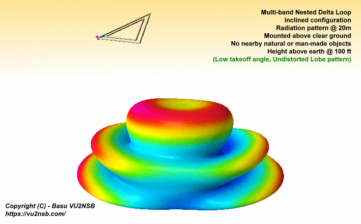
This is a typical scenario #1 where the multi-band inclined nested Delta Loop antenna is deployed in a clear physical space at a height of 100 ft above physical ground with no man-made artifacts like buildings in the vicinity. The radiation lobe pattern is well defined bi-directional in form with great low take-off angle lobes.
The above-depicted radiation pattern closely follows the textbook projections as one might expect. Antenna simulations software would also reflect the same. If one were to presume that an average typical installation of the same antenna in an urban concrete jungle or at a metropolis would produce similar results, then one might be in for a rude shock.
Radio amateurs also often lay emphasis on wire antenna orientation to produce radiation lobes in preferred directions. It is perfectly rational to do so under ideal deployment scenarios or good open surroundings. However, under realistic space-constrained environments under the influence of various surrounding buildings and objects, it may become an exercise in futility.
Scenario #2 (Over the top of a concrete building)
Most non-optimal and space-starved urban installation environments as we often find in urban areas may not only distort the elevation pattern but also grossly skew the azimuth pattern of antenna radiation. Many antennas at supposedly good antenna height above physical ground, as might be presumed, may find that the assumptions may not hold true.The presence of buildings surrounding an antenna around the neighborhood along with the building where the antenna is installed collectively plays a detrimental role resulting in the distortion of its radiation pattern and also a degradation of several other performance characteristics including the realizable gain and overall antenna efficiency. More often than not, an average radio amateur is oblivious to these facts.
A typical urban antenna may have way too much RF energy radiated skywards at high angles and consequently lead to a lower gain in the desired lower angle lobes. The textbook type azimuth lobe directions may also get altered drastically leading to a not so good performance in the expected preferred direction, while unexpectedly better results may occur in other directions.
Here is scenario #2 where the same multi-band nested inclined Delta Loop antenna is deployed on top of a tall concrete apartment building of 85 feet height in a metropolis. The aggregate height of the antenna above the physical ground of the earth’s surface remains identical at 100 ft.
The roof of the building is laid using reinforced cement concrete (RCC) with normal steel mesh embedding. There is an additional small-sized concrete elevator equipment room nearby on the roof. They all contribute towards altering the antenna radiation pattern. The proximity of the rooftop has by far the strongest influence since it tends to act as a secondary ground beneath the antenna structure.
The illustration below shows a simplified overall structural environment along with the effective antenna radiation pattern that one would get under the circumstances. The effects of the water tanks and water pipes laid around the periphery of the roof also play a role.
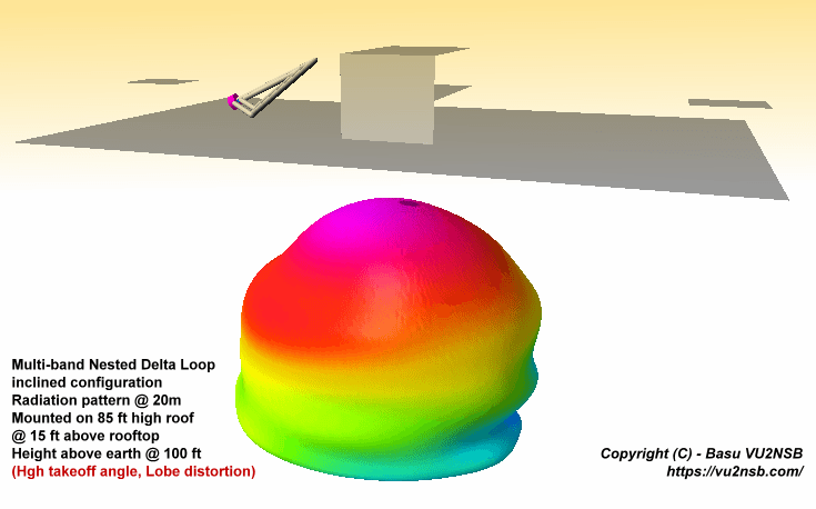
This is a typical scenario #2 where the multi-band inclined nested Delta Loop antenna is deployed on the rooftop of a tall concrete building at a height of 100 ft above physical ground with the roof top acting as a secondary ground along with the influence of other other artifacts in the vicinity. The radiation lobe pattern is quite deformed with the bi-directional characteristics giving way to nearly omnidirectional pattern. A considerable portion of radiation now goes skyward at high angles leaving much less energy to be radiated at lower DX angles.
The resultant radiation pattern in this scenario does in no way anymore resemble the original bi-directional lobe pattern of the same antenna that was earlier deployed in a clear space. Now, the actual pattern is more-or-less omnidirectional with an additional reduction of radiation at low angles in the direction of the elevator machinery room.
Although the antenna deployment still provides very low angle radiation capabilities in almost all azimuth directions, the magnitude of low angle lobes has reduced considerably resulting in far lower low-angle gain than what one might have expected from an equivalent clear space deployment.
The antenna has practically lost its bidirectional properties in favor of becoming omnidirectional. The RF transmitter energy that would normally have gone into strengthening the intensity and consequently the gain at low take-off angles is now diverted significantly in the upward direction. Though the antenna may still work well for DX with perhaps 1-2 S-units inferior performance, it will produce far stronger signals on short-skips and NVIS situations.
Please note, the antenna deployment in scenario #2 has been done very carefully while taking into account ways and means to mitigate the degradation in performance as much as possible, an average urban antenna is usually deployed with far less attention to detail.
Most practical urban antennas might actually yield far greater deviation and more compromised performance in comparison to what this example shows. The examples given in this article were provided to highlight the fact that despite a very good height of urban antennas over the physical ground, the electrical behavior of antennas is greatly influenced by buildings, etc. By no means does this example depict the worst possible scenario. Most antennas deployed in large urban cities and metropolitan areas would be expected to have far greater detrimental patterns distorting influence than what is shown here.
However, antennas mounted on tall towers that allow adequate clearance in all directions including below it, and is taller than all buildings or structures in the vicinity will certainly produce nearly textbook radiation pattern and perform very much as expected as per their specifications. Unfortunately, such a thing is usually a pipe dream of any radio amateur that is rarely achievable by modern urban dwellers… As they say – If wishes were horses, beggars would ride!


(13 votes, Rating: 5.00) - Please vote the article with your valuable star rating. Thanks! Basu (VU2NSB)


SSN SSNf(10.7) – Real-time Solar Data


