

Terrestrial VHF Radio Signal Propagation – LOS
Amateur radio earth-orbiting satellites of the LEO class are regularly accessed by operators around the world using low-power communication gear that put out a few watts, into simple, moderate antennas. These micro and nano LEO satellites also run onboard transmitters that usually put out 1W or less (or a couple of watts at the most), usually into omnidirectional antennas with quite a low gain. Yet, satellite radio contacts are made with ease between the earth stations and the satellite circuits across distances ranging from several hundred to a couple of thousand kilometers. Therefore, why is it that in the case of terrestrial VHF-UHF radio communication, on a more-or-less routine basis, the coverage range is typically limited to only several tens of kilometers? If one is lucky, under favorable Trpopspheric conditions leading to super refraction, etc; one might make it through to a couple of hundred kilometers, but one wouldn’t expect to cover several thousand kilometers on terrestrial VHF-UHF radio… Why? What is it that limits the terrestrial VHF radio signal coverage range? …
Of course, there are multiple reasons. In this article, I will try to, layer-by-layer, peel off some of the mysteries behind this behavior. This article is the first of a two-part series that cover the subject. Here, we will dwell on the concepts of Line-of-sight (LOS) communication losses, while in the following article we will dig into the Beyond-Line-of-sight (BLOS) Trans-horizon VHF radio communication scenarios as well as obstructed LOS situations with hills, mountains, etc that might fall in the way… Read on…
What is unique to Terrestrial VHF-UHF Communication compared to Satellites?
All satellite communication circuits are typically Line-of-Sight (LOS) circuits allowing unobstructed free-space communication. The principle is based on free-space direct Wave communication. Please refer to my earlier article titled VHF/UHF & Free Space propagation for preliminary information.
The free-space Direct Wave propagation path is totally unobstructed and the region around the path is also free-space. There are no nearby objects along the path that could result in reflections and multi-path propagation which could modify the signal strengths. It is nearly a pure form of radio signal propagation that follows Friis Transmission Equation. The path losses are directly proportionate to the square of the distance and square of the signal frequency. To recap from the above-cited article, the typical path loss to be expected in such a LOS propagation path is presented below…
Loss(dB) = 20log(D) + 20log(F) + 32.4
However, unlike free-space LOS satellite, or deep-space communication, terrestrial communications present quite a different scenario altogether, along with a handful of additional factors that contribute towards further compounding the losses on a terrestrial VHF radio circuit. The cumulative effect of all these factors results in magnitudes of path losses that are far higher than what we have in the case of free-space propagation derived from the above equation.
Please note that in this article when we speak of terrestrial VHF-UHF communication, we are dealing with outdoor point-to-point circuits across at least a few kilometers if not more. We are not examining the indoor (within a building) communication scenarios as one would typically encounter in the case of Bluetooth or WiFi.
Let us now enumerate some of the most important factors that cause terrestrial VHF radio signal coverage losses to behave the way they do. Thereafter, in the following section of this article, we will expand upon each of them and explore their cumulative effect on the overall terrestrial VHF radio communication scenario in this two-part article series…
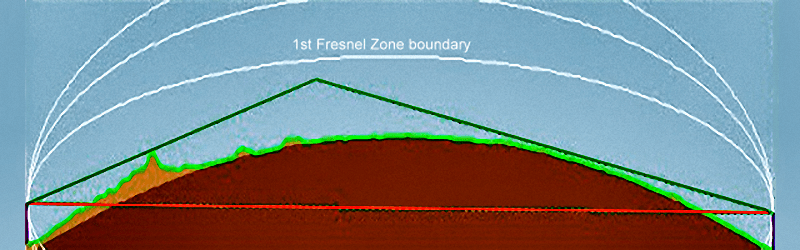
This illustration depicts a list of typical challenges encountered in a long-distance VHF radio signal propagation scenario. The signal has to negotiate the curvature of the earth because the bulge produced by the curvature obstructs the line-of-sight (LOS) path. Fresnel Zone diffraction losses build up and grossly weaken the signal to the receiver. The first white curve trace from the TX to the RX that is shown to pass through the sky is the 1st Fresnel Zone upper boundary. The other upper white traces represent the 2nd and 3rd Fresnel zone limits respectively.
However, these rocks, hills, and other undulations are not the only reason for the terrain obstruction that we all encounter. Even on a perfectly plane and level terrain, we experience the ubiquitous terrain obstruction phenomena… Sounds crazy, doesn’t it? … Yes, perhaps prima-facie it does. Let me explain.
The key to the omnipresent terrain obstruction is the fact that the earth is not flat but spherical. Hence, the terrestrial path from one place to another is always going to be curved like an arc on the periphery of a circle. The greater the distance between the two locations, the greater will be the perceived curvature. Unfortunately, the radio signal would typically propagate in more-or-less a straight line that would be tangential to the curvature of the earth’s surface. As the distance from the originating point (radio transmitter) increases, the amount of divergence of the radio signal from the earth’s surface would become wider. In the sentence above, I used the term “more-or-less straight line”. It was a deliberate choice because, the terrestrial VHF radio signal would usually be subjected to a certain amount of bending along the curvature of the earth due to Tropospheric refractivity gradients, which in turn extends the radio horizon well beyond the optical horizon distance. Read my article on Atmospheric impact on VHF Radio Propagation for a better insight into the subject.
All said and done, the fact of the matter is that the earth’s terrain (even if it is leveled) would present an obstruction between two distant locations due to the bulge of its curvature. The Terrain Bulge of the spherical earth is an omnipresent phenomenon. Geometrically, it becomes more and more obtrusive from the perspective of terrestrial VHF radio signal propagation as the distance increases.
One might logically expect the Terrain Bulge to suddenly and completely cut off the radio signal to locations beyond the bulge. Thankfully, the situation is not all that gloomy. The physical phenomenon of diffraction comes to our rescue. Although the signal would begin to get drastically attenuated with progressive distance beyond the peak of the terrain bulge, yet it might often be strong enough to allow us extended range communication well beyond the obstruction point.
The phenomena of diffraction are strongly applicable to many instances of terrestrial VHF radio signal coverage beyond the shadows of hills and mountains also. In this case, it is called the Knife-edge Diffraction.
Terrain Reflection, Refraction & Diffraction – Radio signals can reflect from a variety of different types of surfaces, just as light reflects from a mirror or sound might reflect to produce echoes and reverberations. The phenomenon of reflection is very common for RF signals. The application of Radar is a typical example where we use reflection to our advantage.
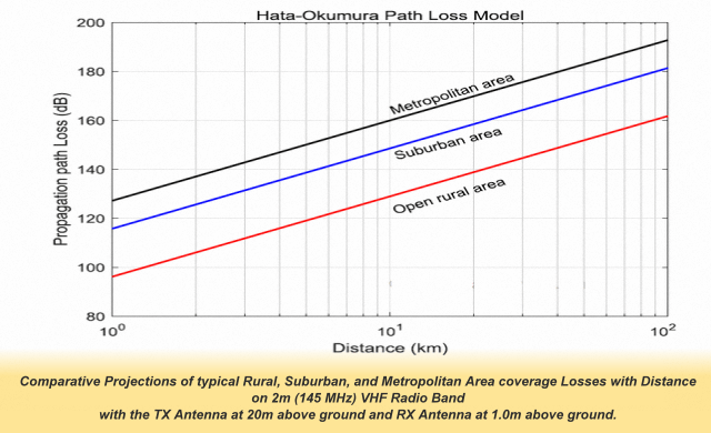
This illustration depicts the average VHF signal propagation loss expected over various distanced in different types of rural, suburban or urban environments.
Very dry, low conductivity materials with uneven surfaces are usually relatively poor reflectors in comparison to smooth and higher conductivity surfaces. Quantitatively, we designate the reflective property by what is termed as the Reflection Co-efficient of the surface.
Moreover, for efficient radio frequency signal reflection to occur, the physical size of the reflecting surface must be several orders of magnitude greater than the wavelength (λ) of the signal to be reflected. That is the reason why most man-made objects like buildings, etc do not usually pose a significant obstruction to radio signals at lower frequencies like medium-wave (MF) or short-wave (HF), however, their size is fairly large to produce reflections at VHF or UHF where the λ is in the range of a couple of meters to several tens of centimeters.
Unlike the case of Radar where we use the reflection phenomena to our advantage, in the case of terrestrial VHF radio we are usually not so fortunate. By and large, reflections play detrimental roles in terrestrial VHF radio communication. The direct radio signal and all other signals reflected from various objects reach the distant receiver location with different amplitudes and phase shifts that are a result of different path lengths. As a consequence, the aggregate vector sum of all the signals that arrive at the RX is usually subject to deep fading or overall attenuation. This kind of reflection loss is a reality for terrestrial VHF radio communication circuits. In the case of fixed VHF radio stations, the reflection losses are usually constant and static, whereas, for mobile radio, it would manifest itself more often as cyclic fading or flutter.
Apart from various types of reflections that could destructively combine with the direct signal to produce undesired attenuation, other factors associated with terrain properties like absorption and diffraction do contribute towards the final receiver end signal strength outcome. Although absorption of radio signal energy like in the case of ground absorption could reduce the effective radiated power from a transmitter, it would rarely produce undesirable effects like fading, flutter, etc. The absorbed power is usually dissipated as heat in the absorbing medium.
Of course, then there is the phenomenon of Tropospheric Refraction. Though this is not a phenomenon related directly to the terrain, yet it is often influenced by the properties of the underlying terrain. Tropospheric refraction has the ability to greatly influence the VHF radio signal coverage range. It is usually what is responsible for occasional unexpectedly long-range VHF radio signal DX coverage… Read more on this topic in the article titled Atmospheric impact on VHF Radio Propagation.
Another very important physical phenomenon that often plays a major role in determining long-distance VHF radio signal propagation prospects is diffraction. This is a phenomenon that we will explore fairly extensively in the course of our discussion. We will focus more on the effects of diffraction in the second article of this two-part series titled as Terrestrial VHF Radio Signal Coverage – BLOS… BLOS stands for Beyond-line-of-Sight.
Unlike absorption or reflection which are quite often counter-productive for radio communication, diffraction is invariably our friend. It provides a unique way of providing signals under very difficult conditions in shadows of man-made and natural topographical artifacts. Diffraction helps in mitigating the problems caused by terrain obstacles that we discussed in the previous sub-section. Although diffracted signals may not be strong, but they act as enablers in a situation when nothing else might work.
At the end of the day, the cumulative effects of all these physical phenomena work in tandem to make or break a communication circuit. The cumulative adverse effects are lesser in rural areas. They progressively become more pronounced in urban areas, and eventually often turn into a nightmare in dense metropolitan regions.
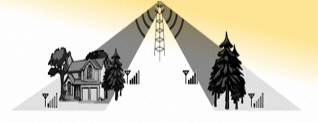
A graphical representation of the typical nature of VHF radio signal attenuation as it penetrates through various objects. A building on one side and a set of trees on the other side would both result in path loss. The levels of signal strength both before and after the obstacles is indicated for clarity of concept.
The challenges posed by the above situation are not so acute in suburban localities and smaller towns where the high-rise buildings are sparse and typical houses are single or double-story with ample spacing between them. In such a situation it is relatively easy to put up a base station antenna on the rooftop that could serve to provide fairly extensive VHF radio communication across the city and beyond.
The real and truly obstinate challenge occurs in denser city environments with high-rise buildings, commercial blocks, office complexes, shopping malls, and apartment blocks that are densely spread all around. Such a city is a big maze of concrete structures. Most VHF radio antennas cannot be put up on top of high-rise buildings due to regulations and logistic issues. Similarly, the mobile and portable VHF radio equipment are almost invariably at or near the ground level on the streets. The terrestrial VHF radio signal range gets drastically curtailed due to all the above factors. Relatively higher TX power and strategically located and duly optimized base-station antennas become a must to extract maximum mileage from a rather difficult situation.
To get a rational sense of what is going on, we need to understand the point-to-point signal propagation scenario under these conditions. Does the signal from one point to another have to pass through the buildings by penetrating the walls one by one as it propagates towards its destination? … One might think, Yes! … It seems logical, doesn’t it? … NO!!! That’s not how it works unless the receiving station is only across a couple of blocks.
In that case, what really happens? … Before we answer this question, let us see as to why the direct path between the TX and RX stations, by cutting through the buildings is not practical beyond a very limited range.
The problem lies in the fact that the VHF radio signal would attenuate by a finite amount each time it has to penetrate a wall of the building. Most of these tall buildings are RCC structures (Reinforced Cement Concrete) comprising of steel embedded concrete columns and beams that form the entire load-bearing structure. This is even though many levels of RCC floors are also laid out in between. The rectangular grid structure formed by the maze of beams and columns also provides sufficiently large gaps. These gaps are like hollow space through which radio signals would logically appear to propagate unabated… Then where is the problem?
Well!, the problem is that these RCC super-structures do not stay that way by the time the building is fully constructed. The outer walls as well as the inner partition walls that eventually lead to the creation of rooms are typically brick and masonry walls of various thicknesses depending on where they are in the building… The building is no more a hollow frame. The brick walls fill these open places.
Let us see what this means. Here are a few basic facts about VHF/UHF signal attenuation through brick walls at 145 MHz (2m) and 436 MHz (70cm), which happen to be the frequency bands of interest to us…
Brick Wall 3.5″ (89mm) thick
Attenuation (2m) = 1.4 dB
Attenuation (70cm) = 2.5 dB
Brick Wall 7″ (178mm) thick
Attenuation (2m) = 2.0 dB
Attenuation (70cm) = 3.5 dB
Let us assume that the VHF or UHF radio signal has to propagate by penetrating through a typical apartment consisting of 2 outer walls (7″ thick) and 3 inner walls (3.5″ thick) that demarcate rooms inside the apartment. That makes it a total of 5 walls per apartment that lie in the propagation path. We will begin by calculating the wall penetration attenuation losses of a building for 2m band VHF radio signal where the losses are far less in comparison to the 70cm band. Of course, later, we will also project losses for a 70cm scenario.
Based on the above data, the aggregate VHF radio signal penetration loss through the apartment would be…
8.2 dB = (2 x 2.0) + (3 x 1.4)
The 8.2 dB derived above represents the typical signal attenuation that would occur due to the need to penetrate and pass through a single small/medium size apartment in an apartment block. Allowing another 1.8 dB (to obtain a round figure and also to add a margin of safety) for miscellaneous losses through the apartment, let us settle a ballpark figure of 10 dB attenuation. Prima-facie, it doesn’t seem to be too bad. We could perhaps afford to have several apartments falling along the propagation path, yet succeed in achieving a strong enough signal at the receiver end. Of course, in rare situations, the attenuation could be worse. In our example, we assumed that the walls are the only obstructions, but keep in mind, if the direction is such where an RCC column (pillar) comes in the way, it may not be so simple.
So far so good… In a scenario with only a few buildings obstructing the VHF radio signal path, it could be fine. However, what would happen if it were to be a metropolitan area with countless blocks of concrete buildings that are laid out densely to form an urban jungle? … It is going to be no more about just a handful of apartments and their walls that need to be penetrated by the signal.
In about one 1 Km distance within a metropolitan area, one might find at least 20-30 inline apartments or blocks that obstruct the signal path. At a conservative estimate of 20 apartments per kilometer, the aggregate attenuation on the 2m band would translate to 20 x 10 = 200 dB. That’s an absolute doomsday scenario. If this is the situation at a 1 Km distance within the metropolis, I shudder to think of what would happen in the case of longer distances.
The 200 dB path attenuation that we derived above is practically unsurmountable with regular VHF communication equipment.
Do not even think of trying it on 70cm. The apartment wall penetration losses would be √(436/145) = 1.734 times greater than what we had on the 2m band. The signal penetration loss through objects is primarily a function of its conductivity, the material permeability, and the square root of the frequency… To avoid confusing the reader, let’s leave it at that for today.
Now, the million-dollar question is how does VHF radio signal communication work in such a dense urban environment? Penetrating through a large number of buildings that obstruct the direct path is obviously ruled out. So, what happens? … We will cover that in the next section of this article.
Vegetation and Foliage – Most of us who live in urban or suburban areas are rarely concerned about vegetation and foliage losses. Extensive deforestation if needed was done before developing the cities. Therefore we normally do not find ourselves amid dense forest vegetation.
However, the terrestrial VHF signal losses caused by vegetation and foliage in large forested areas can be pretty daunting. Hence, we must not ignore it. The magnitude of signal loss would depend on a host of factors which include the density of the forest area, the type and species of trees in the forest, the density of leaves and branches, moisture content of the trees and other vegetation, etc. Moreover, this type of loss increases as a function of the frequency. Higher the frequency, the greater is the loss. Dense tropical forests can make the situation pretty difficult.
To get a rough idea of the nature of losses due to vegetation and foliage, let me quote a few figures out of the CCIR Report 1145. Although the losses at the upper UHF and microwave frequency range may become unacceptably high, we will focus on the 2m and the 70cm bands that concern us. The vegetation loss at 145 MHz (2m) is around 0.04 dB/m, while the loss at 436 MHz (70cm) is around 0.09 dB/m. At first glance, this might look trivial but when multiplied by the actual distance through the forest it quickly begins to become ominous.
Here are a few examples…
Distance within forest area: 1 Km
40 dB loss @ 145 MHz
90 dB loss @ 436 MHz
Distance within forest area: 3 Km
120 dB loss @ 145 MHz
270 dB loss @ 436 MHz
The above examples clearly show that with typical VHF/UHF portable radio communication equipment used inside a dense forest, the coverage distance restriction due to signal absorption by the vegetation becomes quite high. If 2 stations within the forest zone are 1 Km apart, then communication can be maintained on both 2m and 70cm bands. However, at a distance of 3 Km, the UHF link would fail while the VHF link would remain feasible. As a corollary, one could check out to discover that at a distance of 5 Km or more, both VHF and UHF would fail. At higher frequencies in the microwave segment, it would become rather impossible to maintain a communication link at perhaps 0.5 Km or more.
VHF Radio Signal Propagation through Urban Clutter of Large Cities
In the previous section, we had explored the possibility of the VHF radio signal penetrating through the multiple walls of apartments and other building structures in a cascade to reach the destination. However, we discovered that this would not be feasible beyond a point when we might have more than a few buildings in line.
So, the question is, how does VHF radio signal propagate across a large urban segment comprising of a concrete jungle? … Let us see.
Even though the radio signals might have to penetrate a few building walls during its journey, a large part of the radio signal propagation path would generally route itself by skimming over the top of the buildings across the city landscape… For this to work, the principle of Diffraction comes into play.
Here is a very basic example of what would happen. Of course, in reality, it will be far more complex. Multiple diffraction and First Fresnel zone losses over multiple segments will add up cumulatively to produce far greater aggregate losses. However, for, the moment, let us stick to the basics so that we might understand the fundamental concepts.
The following example is supported by the accompanying illustration. Please refer to it to understand how it all works.
From the starting point at the TX end, a part of the signal will travel upwards at a rather steep angle to strike the rooftop edge of a nearby tall building. On striking the edge of the roof, a phenomenon of knife-edge diffraction would occur, thus producing a signal vector that would travel horizontally over the top of this tall building. This diffracted horizontally propagating part of the radio signal will be quite attenuated and far lesser in strength compared to the original signal.
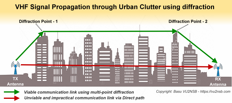
Propagation of VHF/UHF radio signals pose a major challenge in large metropolitan areas due to the nature of the concrete jungle. As discussed below, this illustration graphically depicts a highly simplified concept of how point-to-point radio signals propagate over the city skyline using multi-point diffraction and not along a direct path that would require to perform a practically impossible herculean task of penetrating through the steel and concrete structures of the city.
Typically, a single-point knife-edge diffraction loss (@ 2m or 70cm band) from a building could be anything from around 6-35 dB. This loss magnitude increases in proportion to the diffraction angle (θ). In our case, the angle θ is also equal to the angle of radiation takeoff from the TX rig to the top of the building from where the diffraction would occur. The further one is away from the building from which the signal would diffract, the lesser will be the angle θ which would, in turn, result in lower diffraction point attenuation. Low θ below 10-15° would produce 10-15 dB diffraction loss, whereas, if someone is close to the building wall with about a 60° angle to the building top, it would result in a diffraction loss as high as 32-35dB. Being any closer to the building wall would most likely render the diffraction losses to be unacceptably high for viable communication.
That’s the reason why, one is more likely to lose the signal when walking on a pavement along a row of buildings, while the moment one steps into an open park in the same locality that places the person further away from the buildings, one might begin to receive the signal again.
Therefore, for best results, avoid using a high gain antenna like a tall Omnidirectional Vertical Collinear unless your antenna is strategically located on or well above the tall buildings in your surroundings. Those who have their antennas well below the average surrounding obstructions would stand best chances with higher takeoff angle type antennas even though their gain might be less. After all, there is no point in having a few dB of extra antenna gain if all the low-angle radiated power were to hit the sides of the buildings and get neutralized through absorption. If would rather be far better for a lower gain antenna to throw some worthwhile power at a higher elevation angle to reach the tip of a nearby tall building from where the interesting game of propagation by diffraction could begin…
Let us arbitrarily assume that a 5W signal from a 2m (145 MHz) HT encounters a diffraction loss of (say) 30 dB at the roof edge of the building. This is equivalent to you being on the rooftop of that building instead of your current ground location but with the transmitter putting out 30 dB lesser power (5W / 1000 = 5 mW). This hypothetical transmitter at the rooftop might be assumed to be rated at 5 mW. However, the upside is that this TX signal component (diffracted component) originating from the roof edge would now be traveling horizontally over the city skyline instead of struggling to bulldoze its way through the dense concrete walls of the urban jungle.
OK, let’s move on and see what might happen next… Let us assume that this signal travels horizontally for 5 Km. The free-space path loss over 5 Km can be calculated to 89.6 dB (say 90 dB)… So far we have an aggregate path loss of 30 dB to the TX end diffraction and another 90 dB propagation loss over 5 Km, which totals to 120 dB.
At the far-end 5 Km away, if we have the receiving station somewhere on the ground, then the propagating signal must find a way of reaching it. Another instance of knife-edge diffraction from the edge of the roof of a building near the RX station would now occur. It’s just the reverse of what happened at the TX end. Instead of the TX signal that traveled upwards and diffracted horizontally, now, the horizontally propagating VHF radio signal will encounter the far-end building’s rooftop edge and diffract downwards from there. This would result in another bit of diffraction loss. Let us assume a similar diffraction angle scenario as we had at the TX end. Therefore, another 30 dB attenuation would be produced that would add to the already existing 120 dB that we calculated earlier. This makes a total of 150 dB.
In our simplified example of a two point diffraction based propagation circuit scenario, we land up with 150 dB path attenuation across a 5 KM stretch of metropolitan urban clutter.
Let me remind once again that his example is intended to explain the fundamental process and does not account for several other phenomena like Fresnel zone loss across multiple propagation segments, multi-point diffraction, etc that are associated with typical real and complex situations.
Let us now draw some meaningful inferences from our little exercise so far…
In a city environment, VHF radio receivers would typically be subjected to a fair amount of ambient radio noise. Even though the published RX sensitivities of rigs may claim to be excellent in many cases, the actual realizable sensitivity will be marred by the ambient noise. In a modern urban environment, it would be safe not to expect the RX sensitivity to be any better than -110 dBm in most situations.
Since our calculated path loss is 150 dB, the required TX power to produce the minimum safe level of the signal at the RX will be path loss – RX sensitivity. This is equal to 150 – 110 = 40 dBm.
40 dBm, when converted to Watts, is 10W… Therefore, the 5W VHF radio rig that we assumed in our example will not work for a 5 Km distance range. Although it may well work at 3 Km. The TX power of 10W is the bare minimum needed to work through 5 Km. Similarly, a vehicle-mounted 25W VHF rig would do great with an additional +4 dB SNR margin that would ensure almost full quieting on FM.
Keep in mind that the urban environment may also throw up some pleasant surprises under certain situations. For instance, one might suddenly discover a very strong radio signal along a street that might have originated from a TX location quite far away or from an unexpected location. Such situations are possible due to reflections off the walls of the rows of buildings on both sides of the street. The street might act as a tunnel or a duct that concentrates the radio signal. A street crossing with buildings all around might also at times act as a reflection or diffraction point to steer the signal at a right angle at the street crossing. All these phenomena certainly do occur. They should be treated as a bonus, but they cannot be relied upon to ensure guaranteed access.
In this section, we have discussed the general principles of urban area VHF radio signal propagation. In the following section, let us explore the larger situation of VHF radio signal propagation across wider natural terrains. We will try to discover the effects of various types of terrain obstructions, especially, the omnipresent curvature of the earth that presents itself as a protruded pot-belly, the moment we try to venture beyond the radio horizon. Of course, as I mentioned earlier, we will deal with obstructed LOS paths and trans-horizon BLOS paths in the next part of this article series. For the moment, let us focus our attention back on the unobstructed LOS scenarios and explore it further.
Unobstructed Line-of-Sight (LOS) VHF Radio signal Propagation
A LOS radio communication circuit refers to a typical point-to-point link which is an aggregate of the distance that extends from each (TX & RX) location up to its horizon. The distance to the horizon would of course vary depending on the height of the observation point which in our case would be the height of the antenna. The greater the height of the antenna on either or both sides, the greater would be the LOS distance from horizon-to-horizon.
The LOS distance would therefore consist of two segments, each represented by the horizon distance from each end.
Based on the curvature of the earth, the distance to horizon from each end could be approximated as √(2 x h x Re / 1000), where h is antenna height in meters and Re is earth’s radius in Km. Replacing Re with 6371 Km and simplifying the equation, the horizon distance turns out to be as follows…
Dh = √(12.742 x h) = 3.57 x √h
Extending the above equation to find the horizon-to-horizon LOS distance between two terrestrial VHF radio stations, we have the following…
DLOS = 3.57 x (√ht + √hr)
The above equation gives us the optical LOS distance between two locations. However, typically radio signals unlike light waves are affected by the Tropospheric density gradient of the earth’s atmosphere. Check out this article on Atmospheric impact on VHF Radio Propagation for more information on the subject. Under normal conditions of a standard atmospheric gradient, the above-calculated distance typically gets enhanced by the K-factor of 4/3 (1.333). In our equation, we will need to multiply the optical horizon distance by the square root of 4/3. Let us apply it to the above equation to determine the effective radio horizon distance under standard atmosphere conditions. The final equation for VHF radio LOS distance under the standard atmosphere is…
DLOS = √(4/3) x 3.57 x (√ht + √hr)
DLOS = 4.12 x (√ht + √hr)
where…
DLOS is the radio LOS distance between two stations in Km.
ht is the height of TX antenna in mts.
hr is the height of RX antenna in mts.
In our narrative so far in this section related to unobstructed LOS communication, we have assumed that there is a clear path with no physical obstructions like large buildings, hills, etc between both the point that could obstruct the straight line drawn between the two antennas.
The important property of LOS signal propagation is that the attenuation is low and is limited to free-space direct-wave propagation losses that one might expect to calculate by the Friis Transmission Equation that is given in the early part of this article. However, there is a caveat. The LOS horizon-to-horizon path loss is approximately 6.9 dB more than what is computed by Friss Transmission equation. This is because the LOS horizon-to-horizon path from one antenna to another grazes the earth’s bulge at a tangent. As a consequence, the principle of First Fresnel Zone clearance is grossly violated causing this additional loss. Check out my article on Ground Wave Propagation for more information on Fresnel zone and associated topics. We will elaborate on these factors in the second part of this 2-part article series.
Meanwhile, for those who might be interested, let me leave you with the fundamentals of how to figure out if your VHF radio circuit link meets the 1st Fresnel zone clearance requirements. Of course, this might not always be totally under your control. Even though you might be able to install your antenna at a fair height above ground to mitigate Fresnel zone clearance losses, the station at the other end may not be set up well enough to meet the necessary clearance requirements. Check out the illustration below and apply the associated formulas also given under it to plan your VHF radio station set up. 70cm band VHF radio signal poses a lesser Fresnel zone clearance problem in comparison to the 2m band VHF radio signal. This is because the Fresnel zone radius (central bulge) is inversely proportionate to the square root of the frequency.
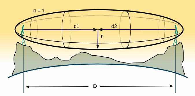
A typical example of Fresnel zone clearance radius at various points along the LOS. Any obstruction within the Fresnel zone region that ensures a clearance of at least 61% will not cause much issues. However, a full clearance is always desirable since it might lead to additional ground reflection gain or “Obstacle Gain: as we often call it. The magnitude of Obstacle Gain will typically be no more than 2-6 dB.
Here is the equation for determining the effective 1st Fresnel zone radius at any distance from either end of the communication circuit. The Fresnel zone radius is maximum at a distance that is half-way along the route when d1 = d2. Thereafter, it progressively reduces as we approach the antenna ends on either side… Here is a simple equation to determine Fresnel zone clearances.
r = √(n x λ x d1 x d2 / d)
Where…
n is the Fresnel zone number. In our case n = 1 because we are exploring the 1st Fresnel zone.
d = d1 + d2
Let us now conclude part-1 of this article series… The longer distance, Beyond-Line-of-Sight (BLOS) which includes situations with obstructed LOS, or Trans-horizon VHF radio signal coverage scenarios is dealt with in the second part of this article series titled Terrestrial VHF Radio Signal Coverage – BLOS.


(17 votes, Rating: 5.00) - Please vote the article with your valuable star rating. Thanks! Basu (VU2NSB)


SSN SSNf(10.7) – Real-time Solar Data


