

Slow Scan TV (SSTV) – Analog and Digital
SSTV had been conceived around the year 1957-1959. It was inspired by the existing Facsimile system known as Radio-Fax. However, it was not practically suited for amateur radio use over HF radio primarily because of the long frame transmission time required for Radio-Fax which was around 20 minutes. Although the frame resolution of Radio-Fax was high, the long transmit time was rather impractical for amateur radio use.
Amateur radio needed to derive a picture transmission protocol that even though might feature lower resolution would require less time and provide a robust transmission over a noisy and hostile HF radio channel.
Genesis & Evolution of SSTV over the last 60 years
Due to the pioneering effort of Copthorne WA2BCW (currently VY2CM), the golden chapter of amateur radio Slow Scan Television (SSTV) came into existence. In the year 1959, he successfully made the first SSTV transmission across the Atlantic ocean was made over the HF amateur radio band. Later, in the year 1964, SSTV was formally recognized as legitimate radio communication mode by FCC and it was permitted on amateur radio bands.
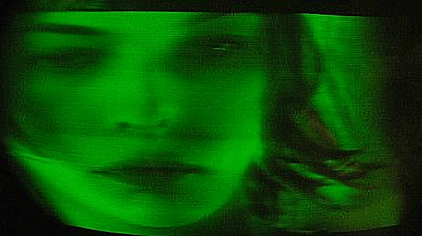
This a how a typical vintage SSTV image appeared on a P7 phosphor CRT display monitor during the early days of amateur radio SSTV.
The earlier experiments during the evolution phase of SSTV, both amplitude modulation (AM) as well as Frequency modulation (FM) were tried. Although they worked, the results were not quite satisfactory. Something else had to be done to overcome the reliability and signal integrity issues to make SSTV more robust.
After considerable experimentation and due diligence, it was discovered that rather than direct signal modulation, a scheme of dual modulation offered the best results. The audio frequency range limited SSTV base-band signal was frequency modulated on another audio frequency. This created a modified base-band signal that was now an FM signal lying entirely within the original AF input spectrum of the SSB transmitter system. This is what we call the FM Sub-carrier. This sub-carrier was thereafter modulated through the regular process by the transceiver to generate either AM, FM, or SSB as may be desired.
Typically, modern HF radio SSTV does an SSB modulation on a preprocessed SSTV FM Sub-carrier. This method is called FM Sub-carrier Modulation. Though it is a slightly more complicated and roundabout method, it provides a far more robust signal integrity over the real-world HF radio propagation medium. Not only is the picture quality preserved better but it also greatly reduces the loss of synchronism of the raster scan line of the SSTV picture.
Other than the sheer inconvenience of the 20 minutes long transmission time of commercial Radio-Fax signals, what really motivated the creation of the amateur radio SSTV protocol was the fact that due to the long transmission time involved, a Radio-Fax transmission required the need for complex precision electro-mechanical photographic paper processors to receive the picture.
Radio amateurs needed a faster frame-rate system that could allow other easily available devices to capture SSTV pictures. One of the few alternatives for use with amateur SSTV was the long-persistent Cathode-Ray Tube (CRT) based receiver. The P7 phosphor-coated CRT which had long-persistence characteristics was readily available. Hence, without dabbling around with complicated electro-mechanical photo printers, radio amateurs could receive the faster frame-rate SSTV pictures on a CRT display. Remember, the personal computers had not arrived on the scene at that time.
My first SSTV setup in 1978 comprised of a self-fabricated photo-transistor based drum-roller picture scanner and an old oscilloscope modified with a 5″ P7 phosphor CRT.
Practical constraints and challenges of SSTV over HF radio
The narrow baseband bandwidth of approximately 3 kHz width SSB transceivers needs to accommodate the SSTV transmission. Unlike the regular broadcast TV that has the luxury of 5-6 MHz channel bandwidth over VHF/UHF, amateur SSTV has its limitations. Hence, in conformity with the Shannon Theory of communication or more precisely the Shannon-Hartley Theorem, it specifies the maximum rate at which information can be transmitted over a communications channel of a specified bandwidth in the presence of noise. Shannon’s channel capacity for a communication link determines the maximum amount of error-free information per unit time that can be transmitted with a specified bandwidth in the presence of the noise interference.
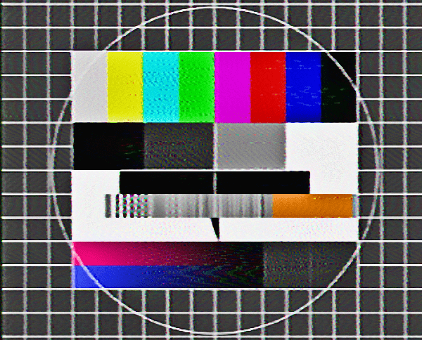
Typical raster of a Slow Scan TV (SSTV) frame. This image depicts a test raster.
This is one of the first constraints of SSTV. Unlike a much higher resolution motion picture that is carried over regular TV, the amateur SSTV needs to be content with a far slower rate transmission that would allow only still pictures to be transmitted. Not only the resolution of the picture frame has to be far less, but the rate at which the frame is transmitted also has to be very slow to conform to Shannon’s theory. As a consequence, a typical SSTV frame with a small size and low resolution would take typically from half a minute to a couple of minutes to transmit. The frame transmission rate for SSTV depends on the protocol used. The slower the transmission rate, the better is its ability to survive in a noisier HF radio environment.
The next factor is the inherent nature of the HF radio channel. It is subjected to the effects of multipath propagation, polarization disorientation, both fast and slow fading (QSB), Ionospheric scintillation and perturbations, various time-spread phenomena, natural noise floor, man-made noise of various types and magnitude, etc. All these make the HF radio propagation environment quite challenging and make it equally difficult to consistently maintain signal integrity as it propagates through the medium.
Although amplitude distortions caused due to noise on AM are rampant, even FM over HF is not so immune. Unpredictable Phase delay, group delay, effects of time-spread, and scintillation can significantly distort FM signals too. Though these distortions do not become apparent or unduly problematic for normal CW or radiotelephony communication, they create major challenges for SSTV as well as various types of digital communication modes. The digital modes often resort to aggressive handshaking and complex forward error correction (FEC) methods along with parity checks to mitigate problems, the amateur analog SSTV does none of these and has to be inherently as robust as possible.
The method of using FM Sub-carrier modulation over SSB for amateur radio analog SSTV is a major step in an effort to mitigate the adverse effects of HF propagation. This is like packing the payload (SSTV raw signal) in a double envelope. The protection from amplitude noise that is the most significant component of an HF radio channel is achieved to a great extent by the nested FM sub-carrier. The dual composite nested modulation scheme also provides a reasonable degree of immunity from other forms of noise.
The anatomy of Analog SSTV signal Subcarrier
An analog SSTV transmission over HF radio is carried out using single-sideband (SSB) amplitude modulation with a general-purpose amateur radio transceiver. The baseband SSTV frequencies above 2500 Hz are strongly suppressed. Since the baseband sub-carrier modulation is FM, the amplitude variations of the baseband signal are represented not by the modulation envelope amplitude but by the variation of frequencies. For instance, the frequency of white color, the maximal level of an SSTV signal, was chosen to be set at 2300 Hz, while 1500 Hz is set for black. the synchronization pulse for frame-sync, as well as line-sync (in case of Asynchronous SSTV), is pulsed to 1200 Hz.
These raw SSTV signals are frequency modulated onto the audio Sub-carrier. As I mentioned before, to avoid any phase shift and drift and maintain quality while eventually propagating over HF, the spectrum of the raw picture signal is modulated on the subcarrier frequency which is chosen as 1900 Hz. The resulting signal is the intermediate Sub-carrier Frequency Modulated (SCFM) baseband signal that would eventually be transmitted after another step of modulation to produce RF SSB SSTV signal.
The frequency of SSTV picture signals varies from black through gray shades to white. The base bandwidth needed for SSTV transmission varies in the range of 1.0 to 3.2 kHz. It also depends on the SSTV mode, transmission speed, and also to some extent on image content.
SSTV Raster and Synchronization format
Similar to regular analog raster scan TV, the analog SSTV also uses the raster scan method for picture capture and reproduction. The primary difference is that in SSTV due to bandwidth limitation, the raster size is smaller with lower effective pixel resolution and the total number of scanned lines is also fewer. The resultant SSTV picture is smaller in size with lower resolution and longer frame transmission duration.Although there are various SSTV modes that have received widespread acceptance, each with some variations in the rater size as well as other characteristics, a typical SSTV raster frame size is 320×240 pixels with a 4:3 aspect ratio. This means that the horizontal size is equivalent to 320 pixels while the vertical size is 240 pixels. Unlike the regular broadcast TV that resorts to interlaced vertical scanning, the SSTV format uses progressive scanning.
The duration of a picture frame transmission depends on the channel bandwidth which in turn determines the line speed. The line speed measured in lines per minute (LPM) depends on the selected SSTV mode. For instance, two modes with an identical resolution of 320×256, the Martin-M1 and Scottie-DX modes have different line speeds of resulting in different frame transmission durations. Martin-M1 with a line speed of 134.4 LPM takes 114 seconds to complete a frame, whereas, Scottie-DX which is more resistant to HF band noise is slower with a line speed of 57.1 LPM takes 269 seconds to transmit a similar frame.
The regular broadcast TV picture frame stability and integrity on the display screen by the use of two types of synchronization pulses that are embedded in the analog signal stream by making the voltage polarity and magnitude of these pulses lower than that of the black level on the luminance scale.
Similarly, SSTV also uses a set of synchronization pulses but instead of making the sync pulse amplitude lower than the black level, in the case of SSTV being an FM sub-carrier modulation, it embeds the sync pulses by making the FM deviation below the black level deviation. Therefore, in view of what we mentioned before that the black level in the SSTV FM sub-carrier is 1500 Hz, the synchronization pulses are modulated to produce deviation down to 1200 Hz. You will get a clearer understanding by looking at the SSTV luminance level diagram that is included further down.
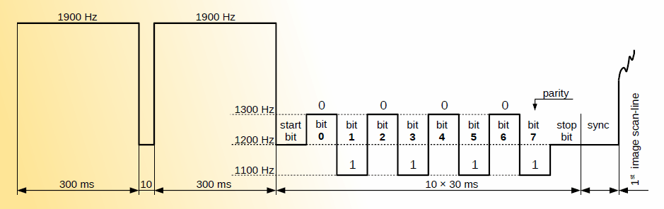
Typical Vertical Interval Signalling block at the start of an SSTV picture frame for synchronization and modulation format identification.
The Asynchronous SSTV is similar to broadcast TV and resorts to both vertical and horizontal synchronization pulses for frame and line sync respectively. On the other hand, Synchronous SSTV (more common in modern amateur radio) uses only vertical synchronization using a start-of-the-frame code block called Vertical Interval Signalling (VIS). This does away with line-sync detection altogether on the receiver end. However, line-sync information is still transmitted by the transmit end of the SSTV circuit.
There are pros and cons of both these methods. The traditional Asynchronous SSTV could be used reproduced on a variety of devices including electro-mechanical photographic exposure devices and analog CRT displays without tearing of images due to mis-synchronism. However, the downside is that the line-sync pulse information often got distorted over the noisy HF bands to render several scan lines unretrievable.
On the other hand, Synchronous SSTV detection ignores the line-sync information but relies on the accuracy of time-synchronization between the transmitter and the receiver. with the use of personal computers (PC), this has become relatively easy. After the VIS header signaling the start of a frame, the native oscillator clocks on the PC at both ends determine reasonable time sync for the duration needed to transmit the full frame. The crystal-derived PC clocks are considered to be stable enough for the purpose. Despite the crystal clocks, we still usually have a problem. The PC clock oscillators may be very stable, yet the precision and accuracy of their settings vary from one PC to another. Therefore, the clock on one PC might be running a tad faster or slower than the other one. This leads to a time-skew. The end result is the slanting of the picture that is progressively formed and displayed on the PC screen at the receiving end.
Before moving on, let us take a quick look at the VIS block at the beginning of an SSTV frame. VIS is used to detect the start of transmission. The receiving device can automatically begin the image scan after vertical sync. All modern SSTV systems adopted the VIS and use these longer syncs and digital headers for automatic SSTV mode recognition.
The VIS contains digital code, the first and last bits are the start and stop bits with 1200 Hz frequency. The remaining 8-bits provide mode identification and contain one parity bit. Each bit is transmitted in order from the least significant bit. Parity is used for simple error checking. SSTV use even parity. This means, that the number of logical ones must be even in the whole 8-bit code. If the number of ones in 7-bits is odd, then the parity bit is set to one. If the number is even, the parity bit is zero. Since the information part of the code has 7-bits, it takes 128 values. The first half of the code (least significant bits, LSB) specifies the type of mode (BW/color, resolution). The second half (most significant bits, MSB) contains information about the system (Robot, Martin, Scottie, AVT, etc). The last bit is reserved for parity error checking.
The VIS code preamble at the start of an SSTV frame not only contains the frame synchronization but also other information related to the SSTV mode, frame size, and other attributes of the picture frame. This helps the software like MMSSTV, etc running on the PC at the receiving end to automatically set itself in a manner that might be required to receive the picture in the particular SSTV mode.
SSTV Luminance and Color signal format
Though the detailed explanation of various alternate schemes used in SSTV for the transmission of all required information related to the Luminance (Brightness) and color composition of a color SSTV picture frame is beyond the scope of this introductory article, I will present a brief explanation here to be followed up by supplementary in-depth articles under this section of the website.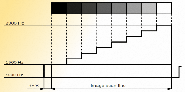
Typical luminance (brightness) scale depiction of frequency deviation as per FM subcarrier modulation scheme.
For a Black and White (BW) Monochromatic SSTV picture, only one signal is needed. It represents the brightness/luminance (Y) of each image element. The frequency ranges from 1,500 Hz (black) to 2,300 Hz (white) transmit image information. Each frequency in this range represents specific brightness (Grayscale).
Typically, human vision can distinguish brightness in a wide range, but can only adapt to the geometric mean value of actual brightness. Around this value, about 100 to 110 grayscale levels can be differentiated. Based on this fact, a transmission with 128 gray-scale levels could be regarded as optimum. For such a signal, an FM sub-carrier frequency resolution of 800/128=6.25 Hz is required. However, we can also manage fairly well for a less bright resolution where it is possible to choose only 64 gray-scale levels thus requiring a frequency resolution of 12.5 Hz.
For the Color SSTV format to reproduce gray-scale properly to ensure compatibility with Monochrome SSTV, we need to resort to a slightly different method. Human vision cannot perceive the brightness levels of all three color components at the same time. When we watch three lights (red, green, and blue) of the same intensity, the human eye perceives the green light as the brightest. Red and blue are not as bright in our perception. Due to this, the gray-scale levels for equivalent luminance perception need to be created using the following well-researched paradigm generated from R, G, B (Red, Green, blue) components of the color picture.
Y = 0.30R + 0.59G + 0.11B
The largest factor 0.59 is for the green, so 59 % of colors that we can see depend on the green component and only 30 % is of the red and 11% for the blue components. The resulting luminance level (Y) created by the above-cited weighting factors on RGB components appear to be very similar to that of a BW picture. Hence, compatibility between BW and Color SSTV is achieved.
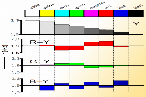
Composite Color mixing model to generate YCrCb type color format in SSTV subcarrier modulation.
The Additive Color model produces all other colors by combining these three primary colors (R, G, B). On the transmitter side, all colors are resolved into the three RGB primary colors and transmitted together. On the receiver side, they are recombined to recreate the original color scheme of the picture frame.
However, in reality, the process is perhaps not as simple. Since the human eye is most sensitive to green, the largest part of the line takes just this part and the remainder is filled with red and blue parts. For instance, the ratio might be 4:2:2 for G:R:B; or else it could even be 4:2:0. We will not dwell deeper into this aspect and will leave the discussion on the finer nuances of SSTV signal composition for a separate article.
The additive color model is a method of SSTV transmission that takes more time to transmit, but it allows a transfer of true colors.
The second type of colour SSTV transmission is the Composite Color Model. It is also called the YCrCb format. In fact, it is a similar system as is used in color fast-scan television, where each color component R, G, B, are transformed to Luminance and Chrominance (color information) signals. Unlike the other Additive Color RGB model, the transmission time of an image is relatively shorter.
In this method, the image scan-line containing the colors is transformed into two components, Luminance and Chrominance. The chrominance signal is composed of two differential color signals R-Y and B-Y. Signal Y is called luminance and contains the signal containing the brightness information according to the RGB equation cited earlier.
On the receiver side of the composite color signal, the three primary colors R, G, and B are segregated by the following method of simply subtracting various transmitted signal components from one another.
R = (R-Y) + Y
B = (B-Y) + Y
G = Y – 0.51(R-Y) – 0.19(B-Y)
The Color Composite (YCrCb) format of SSTV transmission takes approximately half the time, yet produces almost the same image quality. However, the downside is that a more precise transceiver tuning is needed, otherwise, the color information gets distorted. SSTV systems using Composite Color model (YCrCb) transmission are also less resistant to interference prevalent in the HF radio propagation medium in comparison to their RGB counterparts. These are some of the reasons why the YCrCb encoding is used less frequently.
Amateur radio Analog SSTV modulation standards
Typically, the earlier amateur radio SSTV transmissions were displayed on long persistent monitors with P7 phosphor CRT. The duration of transmission for each frame was standardized at either 7.2 to 8 seconds. The 7.2-second standard was popular in Europe and Asia while the 8-second standard was used in America. This allowed easy synchronization based on 50 Hz or 60 Hz mains utility supply. The short transmission time was used to ensure that when the last line was received the first line was still visible. It was possible to see the whole picture in a darkened room on a P7 phosphor CRT. The disadvantages of the old 7.2/8s SSTV were very low frame resolution and being more prone to loss of synchronization due to noise and interference. The loss of synchronization could lead to the loss of a few lines or even the entire image.
The earliest color SSTV pictures were transmitted by what is called Frame Sequential Transfer. Three 8s frames of RGB segregated color information were transmitted sequentially, one after another. At the receiver, all three frames were stored and thereafter combined to reproduce the color picture. The type of transmission was not always reliable due to interference and fade-outs. The frame component had to be sent several times before a full acceptable quality image could be reconstructed. In practice, it was sometimes problematic to receive all three color channels to complete the QSO.
To mitigate these issues, modern SSTV transmission methods use the Line Sequential transfer method. The principle is that it transmits a single image where each scan-line carries all three color components. Hence, an on-screen progressively building of image at the receiver displays the progressive picture buildup in color. This method where the color image is transferred in one frame is referred to as Single Frame Color (SFC) format.
Modern SSTV protocol standards as in use today have evolved over a period of time, thanks to extensive work done by individuals like Martin Emmerson (G3OQD) and Eddy Murphy (GM3SBC), and also firms like Wraase Electronics GmbH, Germany, and Robot Research Inc. USA and many other people. As a consequence, today, we have a plethora of standard formats available to us with varying degrees of strengths and shortcomings. By and large, they all work well and are suited for analog SSTV under a variety of communication environments.
Here are some of the more prominent analog SSTV standards available to us. The offered modes may be Monochromatic or color, Additive or Composite color system, relatively fast or slower transfer rates, some suited either for noisy HF DX or others for less hostile VHF/UHF environment, etc.
The list of some of the most commonly used SSTV protocol standards along with important parameters is listed in the table below for reference.

A chart of popular amateur radio analog SSTV modes with typical parameters that distinguish them on the basis of their protocols.
Several Martin, Scottie, and Robot modes are very popular among radio amateurs for use over the HF radio bands. Martin HQ1 & HQ2 modes have also gained popularity over the years. These modes use the composite Color method against the RGB method used by all other Martin protocols. Quite often the transmission time and resolution offered by a specific mode determine the choice during various band conditions. Scottie DX mode is a rather robust mode for use under relatively noisy and weak-signal HF radio conditions. Although out of all the above-listed mode it takes the longest time to transfer a picture frame, it is worth choosing Scottie DX under difficult propagation conditions.
Other than what we have discussed above, there are several other less widespread SSTV modes including a few experimental modes.
Operating analog SSTV over amateur radio

The frame depicted on the left represents a progressive forward-slanting of received frame due to slower sampling clock rate at the receiver. The righthand frame depicts a reverse direction slanting due to a faster sampling clock.
However, there is quite often a small issue related to SSTV reception that might require operator intervention to do some correction. Since most SSTV modes use synchronous detection mode during picture frame reconstruction, the horizontal line-sync information is never used. The system depends on the accuracy of matching of the PC hardware clock frequencies between the PC hardware at the TX and RX ends of the circuit. This may often not be true.
Usually, there are slight inaccuracies in the factory settings of PC timing clocks. This may lead to a progressively increasing timing difference between the transmitted picture frame and the synchronously received frame at the other end. The cumulative effect of time difference may lead to the received picture frame from producing a skewed image (non-rectangular) by either slanting forward or backward depending on whether the receiver side PC clock is faster or slower than the TX side PC. The timing is derived from a sample rate that may not be exactly 11,025.00 Hz but often can differ up to a few tenths of a percent for each piece of hardware. For speech and music processing it doesn’t matter, but in the free-run transmission of SSTV, it causes problems.
Due to the above reasons, most SSTV software allows the operator to either perform corrections by introducing clock offset during the reception or to allow the user to do a post-reception slant correction. Asynchronous type SSTV receivers do not suffer from this problem, however, they could be more susceptible to detrimental effects of channel noise.
A variety of analog SSTV software is available for running on practically every PC operating system. Some of the popular ones are…
- MMSSTV (MM Hamsoft) – for Windows
- MixW V3 – for windows
- Digital Master 780 (HRD Suite) – for Windows
- SSTV FAX WX Software – for Windows
- QSSTV – for Linux
- MULTISCAN 3B SSTV – for Apple MacOS
- SSTV – for iOS
The most popular SSTV software today is perhaps MMSSTV. It supports multiple protocols and modes with automatic detection capability. A typical setup requires a PC running an SSTV transmitting and receiving software to generate and process the FM sub-carrier audio baseband signal. The PC is connected to the HF transceiver using an AF interface cable. The transceiver finally modulates the incoming sub-carrier signal to produce HF band SSB. For VHF/UHF use, the final modulation could be SSB or FM.
Digital SSTV (DSSTV) for radio amateurs
Transmission of digitized pictures over HF radio is referred to as Digital SSTV among the ham radio community. However, this parlance may not always be appropriate specifically for the methods typically used in amateur radio. There are several gray areas.
 - How it works 1")
Digital SSTV software Easypal that is used frequently by radio amateurs.
Of the several digital SSTV software that is available, the two most prominent ones are KG-STV and Easypal. KG-STV is perhaps the one that qualifies close enough as digital SSTV because it uses a protocol that is very nearly like a normal TV with a left-to-right and top-to-bottom picture scanning system. It transmits in blocks of 16×16 pixels and builds the picture at the receiving-end screen gradually like typical SSTV. The entire picture is transmitted over the radio and uses the MSK or 4LFSK modulation scheme.
On the other hand, Easypal is partly not really what a purist might term SSTV. It offers two modes of transmission. The first one is the normal (over the air) mode which is actually DRM (File transfer). It is similar to regular digital file transmission and in no way mimics raster scanning. The second mode of Easypal is called the Hybrid mode. In this mode, it does not even transmit the picture over the radio. The software uploads a picture over the internet to a designated FTP server and thereafter only sends the FTP URL (link) to the receiving station over HF radio. After receiving the link, the receiving station software downloads the picture via FTP over the internet and displays it on the screen. This is not even a picture transmission over the radio, let alone being SSTV.
We will dwell on the finer aspects of DSSTV in another article.
 - How it works 2")

(20 votes, Rating: 5.00) - Please vote the article with your valuable star rating. Thanks! Basu (VU2NSB)


SSN SSNf(10.7) – Real-time Solar Data


