

Effects of Local Ambient QRM on HF Radio
Although these problems could be mitigated to a large extent by carefully choosing and setting up the antenna system, the unfortunate fact is that many radio amateurs do not even realize how or why these factors affect the radio station performance. The usual trend is to set up the antenna, use a low-loss coaxial cable which has become a fad these days, adjust the SWR to as low as possible either directly or using an ATU, and bingo! … They now have a false sense of security that leads them to believe that they have an optimum setup at their disposal… Unfortunately, it is far from the truth. After having achieved these above-cited criteria, they would begin to make contacts using ultra weak-signal modes like the FT8, to be blissfully content that they might be working great DX. That’s not how it should be. The real fun is to be able to work either SSB radiotelephony or at least CW into all those areas that one might be able to reach with FT8… Is it possible? Yes, quite often it could very well be possible. Let us try to understand the limiting factors that might prevent this from happening.
It is true that mother nature might be responsible for some of the bottlenecks. For instance, at the time of writing this article (March 2021), we have just entered the beginning at the bottom of Solar Cycle #25. Therefore, currently, the SSN and SFI are both fairly low. This may not be conducive for robust QSOs with strong signals across the world most of the time, however, even these low SSN conditions do offer several band opening for HF radio DX on a daily basis, irrespective of which part of the world one might be located in. That too on either CW or SSB voice and not just FT8.
I concede that propagation conditions due to low SSN might not present a cakewalk but it does not mean that HF SSB radiotelephony is off the charts… The most stubborn factor that results in a lack of SSB voice communication DX prospects is not really the low SSN factor. In reality, it is usually the high adverse susceptibility of your antenna setup to the surrounding local ambient noise environment that kills the prospects… In this article, I will try to explain the adverse effects of local QRM on a radio station’s performance capabilities.
If you cannot hear them, you cannot work them!
That’s the fundamental point… If you can’t hear them, you can’t work them. Therefore, the first and foremost factor is your ability to hear the other station. Unless the DX is running a kilowatt or more (which is relatively rare) while you are running barefoot (~100W PEP), the chances are very bright that if you hear him, he will hear you too.
This brings us to the vital question. Why can’t I frequently enough hear the DX stations on my HF radio? All I hear is background hash noise. I am using a modern rig like an Icom IC-7300 or a Yaesu FT-991A with a waterfall display, yet I rarely see any activity at all… Why? … Well, more often than not, it might have to do with the unacceptably high noise floor on your receiver. This messes up the DX station’s SNR and ends up drowning the signal in the noise.
- Make sure that you are listening to a band that has prospective propagation opening from your QTH at that time of the day. If you do not know how to figure it out, read the articles on propagation on this website, especially, the article titled Radio Propagation Forecasting.
- Do not reduce the RF Gain of your transceiver with an effort to cut off the background HF noise. Keep the RF gain at the highest level unless you have a very strong signal to deal with. Learn to get used to the background noise. It is the life-blood of HF radio. By reducing the RF Gain, you are simply reducing the receiver front-end sensitivity. What’s the point of spending money on a highly sensitive rig if you were to willfully kill that feature? Don’t do it.
- Many transceivers can switch in various filters. These filters have different signal processing bandwidths. Modern DSP-based TXRs are more flexible as they allow you to program and set the effective detection bandwidth you might want. If you notice a difficulty to copy weak-signal, then reduce the filter width for enhanced comprehension. Reduction in filter width improves the signal-to-Noise Ratio (SNR). Although if you cut the bandwidth to 1.8 KHz or lower for SSB, it might make the voice sound less natural, however, it’s worth it while working weak-signal DX. It improves overall intelligibility. If you want to be an expert DXer, then learn to work comfortably with narrow filter widths.
- If you wish to be a good DXer, then do not waste money on fancy speakers for your ham shack. Get yourself a good pair of headphones instead. It will go a long way to let you work difficult HF DX.
- Do not go out of your way to deck up your ham shack with fancy electric lighting to make it look sexy. Most modern LED lights, CFL lights, as well as regular fluorescent lights with electronic ballasts are notorious noise sources. Avoid them. It’s your choice whether you want your shack to look wow for your friends and relatives, or you want it to be truly effective and functional for good DX work.
After having briefly listed some of the important factors that an HF radio operator ought to pay attention to, let us return our focus to the core issue that we are addressing in this article.
Do I need to optimize my antenna to mitigate local ambient QRM?
Oh yeah! … You bet you do. However, in this article, I am not going to cover the ways and means of optimizing the antenna setups. Instead, I will focus on the common adverse effects and how they compromise our HF radio DX capabilities, often rendering our amateur radio stations into quite pathetic performers. I have already written several articles on that aspect of how to improve your antenna setups. Please refer to 100W on a Wire Antenna – How far would it reach?, and also Are HF Bands Really Dead during Low SSN at Solar Cycle Minima?.
Let us now get down to some facts. The International Telecommunication Union (ITU) has conducted extensive studies on noise conditions prevailing on the HF radio spectrum. This includes both natural noise (QRN) due to galactic sources, atmospheric entropy thermal noise, weather factors, etc., as well as various types of man-made noise (QRM), etc. ITU has published various detailed technical reports on these aspects. Man-made noise (QRM) levels have been classified into several groups based on the types of human settlements. For instance, based on ITU findings, the QRM levels may be classified into Quiet Rural, Rural, Suburban, Urban, business (Industrial) districts, etc. These are some of the classification blocks that I have used for this article.
While the natural noise (QRN) is more-or-less consistent during a specific solar cycle phase, local time of day, on any particular frequency band, etc.; the man-made noise (QRM) would vary within a particular region depending on whether it is an urban or a rural area and so forth. Therefore we need to find the effects of our dwelling environment on HF radio communication.
Some people might still ask, what difference does it make? Maybe the radio reception at my QTH would be a little noisier but what’s the big deal? … Then some might say, aha! how about using the Noise Reduction (NR) feature of my modern rig? My rig has an expensive DSP-based NR feature. That will take care of all the noise. Won’t it? … NO, sadly it won’t… Why not? Well, I will explain DSP NR and what it can do as well as what it can’t in a separate article.
For the time being bear with me. Let us briefly understand the concept of signal-to-Noise Ratio (SNR) as presented at the transceiver antenna input while receiving. The SNR is on account of ratio of the Signal Power (PSig) at the antenna terminal to the sum total of the Natural Noise Power (PQRN) and th Man-made Noise (PQRM)… Hence, the SNR = PSig / (PQRN + PQRM). Usually, the SNR is expressed in decibels (dB) after subjecting the ratio cited above through a logarithmic conversion process.
Typically, for the radio signal to be readable, the signal power must be at least slightly greater than the total noise power. Hence, theoretically, SNR must be > 0 dB. However, in the real-world signal detection and decoding scenario, the SNR needs to be considerably better than 0 dB. Since, in this article, we are focusing on prospects of SSB radiotelephony, let us take that as an example. A 1-3 dB SNR might be copyable under a stable and QSB free HF propagation environment. For a robust copy with various degrees of reliability, one might want 6-12 dB SNR. Whatever might be the case in question, the bottom line is that the lower the SNR, the lesser is the prospect of copying the DX signal. In other words, the higher the ambient noise at the antenna, the lesser are the possibilities of establishing radio contact.
As they say that a picture is worth a thousand words, let me present you with a few graphical renderings of typical propagation conditions as was expected from my home QTH in New Delhi, India on the 18th March 2021 at around 13:00 UTC on the 20m HF band. These graphics would serve as a set of examples showing what might happen as the Man-made Noise (QRM) levels were to change as if my QTH was located at different QRM zones like Rural, Suburban, Urban, etc… We will see below how different ambient QRM noise levels would alter communication prospects across the world. Please note that the Ambient QRM levels that we refer to, are not due to any single local high-intensity repetitive pulse noise source, etc. The Ambient QRM is on account of a Gaussian aggregation of multiple electrical noise sources resulting in a general elevation of the average background hash noise levels. The noise is almost homogeneously mixed with the signal and cannot be removed using typical methods like noise blankers, etc.
Although the set of graphics that I present are based on my home QTH scenario, the adverse influence of the phenomena that I have highlighted will pan out in a similar manner irrespective of your respective geographic locations.
A well-designed, well-deployed dipole antenna with a proper Balun transformation at the antenna feed-point is the primary reference antenna used in our study. The antenna produces a negligible common-Mode Current (CMC) on the coaxial cable transmission line.
The first five scenarios below use the above-cited dipole antenna. The sixth graphic uses an EFHW antenna with identical height above ground level as well as identical gain. The only difference is that, unlike the dipole which has very low CMC, the EFHW antenna has a rather significant undesirable CMC on the transmission line… Observe in the case of the EFHW antenna, due to elevated CMC on the coaxial cable, the DX coverage is very adversely affected. Despite well-tuned, low SWR setups, the higher CMC turns out to be the culprit.
Here are the results of HF radio propagation prospects on the 20m band under various types of man-made electrical noise environments. Read the associated caption-text against each graphic. If you observe carefully, you will note that the DX propagation conditions into Europe, Africa, and parts of Australia are the best and strongest in the case of a Quiet Rural location shown in figure #1. Progressively as we look through figures #2, #3, #4, #5, etc., we find that the red/orange tinge in the illustration maps (denoting propagation) begins to fade away from many DX regions as we simulate higher QRM levels as would be expected in suburban, Urban, and Business district areas. Finally, figure #6 brings out the worst scenario where the DX coverage is rather disastrously poor. This is because we changed the antenna to a type where the transmission line CMC is more difficult to tame… Rest should be self-explanatory…
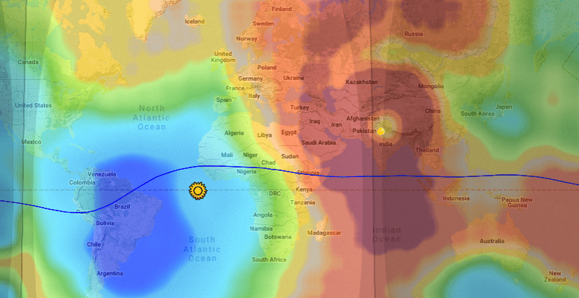
FIGURE #1 – (Quiet Rural Location): – The HF radio propagation prospects on 20m band as on 18th March 2021 from New Delhi, India.
Antenna: – Dipole
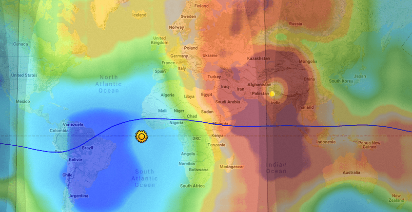
FIGURE #2 – (Normal Rural Location): – The HF radio propagation prospects on 20m band as on 18th March 2021 from New Delhi, India.
Antenna: – Dipole
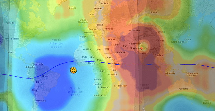
FIGURE #3 – (Suburban Location): – The HF radio propagation prospects on 20m band as on 18th March 2021 from New Delhi, India.
Antenna: – Dipole

FIGURE #4 – (Urban Location): – The HF radio propagation prospects on 20m band as on 18th March 2021 from New Delhi, India.
Antenna: – Dipole
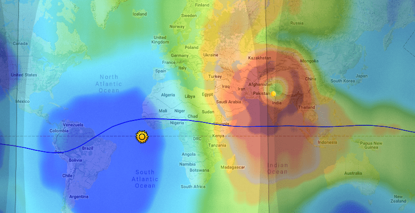
FIGURE #5 – (Business District): – The HF radio propagation prospects on 20m band as on 18th March 2021 from New Delhi, India.
Antenna: – Dipole
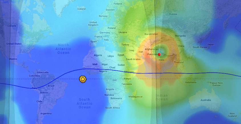
FIGURE #6 – (Urban Location): – The HF radio propagation prospects on 20m band as on 18th March 2021 from New Delhi, India.
Antenna: – EFHW with unacceptable CMC
Recap of how a poor antenna choice kills DX under urban ambient QRM
Before we wind up this article let me leave you with a graphical rendition of expected DX coverage under urban local ambient QRM conditions. The animation shows a comparison of two situations, one using a well-balanced dipole antenna system while the other uses an EFHW antenna with a rather compromised system with elevated CMC on the transmission line... Draw your conclusions.

Comparison between two antennas both operating under identical circumstances on the same band during the same time of the day. One is a dipole with excellent Common-Mode Current (CMC) suppression, while the other is a highly unbalanced end-Fed antenna with relatively much poorer CMC suppression on the coaxial cable feeder. This illustration graphically depicts the implications of CMC suppression on the overall SNR performance at the receiver.
The associated animated graphic clearly shows a big difference in DX prospects even though both the dipole as well as the EFHW antenna have nearly identical gain and radiation takeoff angles. Both the antennas are tuned for optimum SWR. The example is rendered around my home QTH in New Delhi, India. A similar performance difference would be expected irrespective of your geographic location.
The colored maps display the SNR of signals received from around the world. The red, orange, and yellowish colored areas are the places that are accessible from my QTH for comfortable CW or SSB voice QSO, whereas, the greenish, cyan, and blue colored regions are practically inaccessible. The signal from a station in these regions would be uncopyable due to unacceptably low SNR... Notice the difference in the prospective coverage areas between the dipole and the EFHW antenna.
The bottom line is that unless the antenna system has a low CMC on the feeder, then DX prospects go for a toss as the local ambient QRM overshadows the signal. People living in low QRM rural areas do not have much to worry about despite a bit higher CMC, however, for those of us who live in urban areas, the taming of CMC is a game-changer.


(14 votes, Rating: 5.00) - Please vote the article with your valuable star rating. Thanks! Basu (VU2NSB)


SSN SSNf(10.7) – Real-time Solar Data


