

High Gain HF Preamplifier for Weak Signal DX?
On various amateur radio forums, Facebook groups, as well as during personal interactions I have come across people who believe that adding a preamplifier to their HF radio rigs might improve their weak-signal DX prospects. Let us try to examine why such a notion is unsustainable and incorrect. We will also briefly examine why a preamplifier makes sense for VHF/UHF or microwave. What is it that sets HF apart from the higher frequency bands?
Recap of Noise levels in Radio Communication Environment
The prevalent noise levels in a communication system environment determine the limit of the weakest signal that could be copied. Essentially, the background hash noise that is more-or-less persistent over a communication circuit on any band and during a specific time of day or season is white noise. In other words, the power density of the noise is nearly uniform over any band of frequencies. The aggregate noise experienced by a receiving station is made of the noise generated by the receiving equipment hardware and more significantly the noise generated in the propagation medium.
The noise produced by the receiver hardware may be controlled and minimized in the equipment design to a level limited by the state-of-art in technology. However, the extraneous noise coming from the propagation medium may not be easy to control. These noise sources may be either natural or man-made.
The magnitude of the noise density that is produced by the propagation medium from both natural sources and man-made sources is typically much higher at HF than at VHF/UHF or microwave. The HF band noise is generally several orders of magnitude higher in strength than that on the shorter wavelength bands.
The above-mentioned factor is primarily the reason why HF band preamplifiers are usually pointless. Let us expand on this and try to understand it better. Those who might like to attain a better insight into the sources and the noise power distribution characteristics in a radio communication environment might like to read our article Noise in Radio Communication.
Signal-to-Noise Ratio (SNR) and Noise Threshold
First and foremost, there are a few basic points related to noise levels in a communication scenario that we ought to keep in mind.
- The signal-to-Noise Ratio (SNR) has to be positive over the required channel bandwidth (detection bandwidth). In other words, the magnitude of the signal must be greater than the aggregate noise.
- The noise level magnitude is the limiting factor that determines the lowest possible detectable and usable signal strength at a receiver location.
- The higher the aggregate noise at the receiver input, the greater would be the received signal power level required to achieve a positive SNR value.
- The prevailing noise level determines the limiting threshold for weak-signal communication.
- The aggregate of noise produced by natural and man-made sources normalized (as reflected) to the receiver input determines the above-cited threshold.
Characteristics of Noise at Receiver Input
The aggregate noise that is present at a receiver input comprises of two basic types. The radio receiver electronic hardware generated Thermal Noise and the aggregation of noise from extraneous sources as picked up by the antenna and presented at the receiver input. We will refer to this extraneous noise as Antenna Noise. The magnitude of both these noise types adds up to present a composite noise-limited threshold as seen at the receiver input.
The Antenna Noise (extraneous) is dependent on the frequency band of operation. Typically, if we were to examine, we will find that the magnitude of antenna noise is much higher at HF and its magnitude progressively reduces as we move to higher frequencies in the VHF/UHF region. On the other hand, the Receiver Noise that is produced due to the electrical thermal noise of the receiver hardware is fairly low and controlled by the designer of the equipment. Modern electronic components allow low noise receivers to be built with ease. Without even making any special effort to minimize receiver noise, the modern run-of-the-mill receiver would rarely have an input Noise Figure (NF) greater than 3-5 dB. Even the properly designed older receivers could easily attain around 5-8 dB NF. Having said that, modern receiver designs can quite easily strive to achieve a Noise Figure as low as 0.5-0.8 dB if the designer chooses to do so. All this can be done using fairly inexpensive components.
At this stage, let me present the following graph that represents the noise distribution from natural extraneous sources. Though in this narrative we are primarily interested in the HF band noise, the graph covers a frequency range from 10 kHz to 100 MHz. I have ignored the man-made noise sources so as to present the worst-case (minimum noise) scenario. The addition of mn-made noise would only have further elevated noise levels thus making the argument of using preamplifiers even more irrelevant.
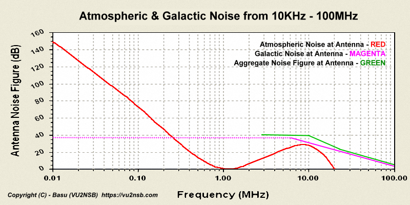
Natural atmospheric and galactic noise across the radio frequency spectrum from 10KHz – 100MHz. The Green colored curve designates the aggregate noise levels in terms of antenna noise figure (NFa).
At the HF frequency bands, the overall aggregate noise is dominated by the Antenna Noise (Na) since it happens to be several orders of magnitude greater than the typical Receiver Noise (Nr). However, as we move higher in frequency from VHF to UHF and beyond, the quantum of Antenna Noise reduces at a rapid pace till it becomes comparable to the Receiver Noise produced by the hardware of low noise receiver with GaAs or HEMT front-end.
Before we proceed further, let us summarize the key takeaways from our discussion so far…
- Since the Noise floor at HF is high, it is pointless to have a receiver sensitivity greater than that of the noise floor level. It will only enhance the noise without doing any good to the SNR. Hence, a preamplifier is uncalled for.
- The dominant contributor to noise on HF is the Antenna noise. Hence, using a low noise preamplifier will serve no useful purpose because the overall aggregate noise will be practically dictated by the antenna noise and not the receiver noise.
- At VHF/UHF and beyond, the aggregate noise floor is low. Hence, the additional gain provided by a preamplifier may come in handy.
- At VHF/UHF and beyond, the antenna noise is comparable to the receiver noise. Hence, a reduction of receiver noise by virtue of a low noise front-end might contribute favorably towards overall performance enhancement by reducing the overall noise.
Receiver Noise Figure (NF) and its effect on performance
The receiver noise figure is a reflection of the overall receiver contributed thermal noise as seen at the input antenna terminals of the receiver. The Noise Figure (NF) is one of the several ways of designating the receiver noise characteristics. The other common designators are Noise Factor (F) or Noise Temperature (T). They all represent the same thing in different ways with different units of measurement. The NF, F, and T are all mathematically related and can be converted from one to the other.
Although working with Noise Temperature with Ta for Antenna Noise Temperature, Tr for Receiver Noise Temperature (in lieu of NF), and Ts for the composite System noise Temperature is perhaps more convenient, we will use Noise figure (NF) in our narrative because it is more commonly understood by radio amateurs.
In the graph given above, I have designated the typically used Antenna Noise Temperature in terms of equivalent Antenna Noise Figure (NF) on the Y-axis scale to make it easy for correlating with the Receiver Noise figure. Now, the question is how do both these noise figures influence the overall outcome of the System Noise Figure?… Let us examine.
Without going into the mathematical derivation of equations, let me present the final equation that is of interest to our narrative.
NFs = 10Log(10(NFa/10) + 10(NFr/10))
Where…
NFs = Composite overall System Noise figure.
NFa = Antenna Noise figure from the graph.
NFr = Receiver hardware Noise figure.
Now, let us first apply the above equation to calculate a few typical HF radio band system noise figure NFs for standard amateur radio receivers with typical noise figures NFr in the presence of antenna noise given by NFa. We will see that the adverse effect of receiver NF is practically negligible across the entire HF band even when we use stock amateur radio transceivers or receivers that typically have NFr in the range of 3-5 dB with around 8-10 dB for poor rigs.
80m HF band which is expected to have NFa = 40 dB
NFr = 8 dB — Then calculated overall NFs = 40.0 dB
NFr = 5 dB — Then calculated overall NFs = 40.0 dB
NFr = 3 dB — Then calculated overall NFs = 40.0 dB
40m HF band which is expected to have NFa = 40 dB
NFr = 8 dB — Then calculated overall NFs = 40.0 dB
NFr = 5 dB — Then calculated overall NFs = 40.0 dB
NFr = 3 dB — Then calculated overall NFs = 40.0 dB
20m HF band which is expected to have NFa = 25 dB
NFr = 8 dB — Then calculated overall NFs = 25.1 dB
NFr = 5 dB — Then calculated overall NFs = 25.0 dB
NFr = 3 dB — Then calculated overall NFs = 25.0 dB
10m HF band which is expected to have NFa = 20 dB
NFr = 8 dB — Then calculated overall NFs = 20.3 dB
NFr = 5 dB — Then calculated overall NFs = 20.1 dB
NFr = 3 dB — Then calculated overall NFs = 20.1 dB
We find from the above calculations that there is practically no deterioration of the composite noise figure (NFs) on account of the stock transceiver’s front-end input noise figure (NFr). The original antenna noise figure (NFa) is preserved. Hence, an addition of an outboard low noise preamplifier will serve absolutely no purpose.
The fact of the matter is that almost invariably an external RF preamplifier when used with any decent HF transceiver or communication receiver only serves to increase both the signal and the aggregate background noise in equal proportion. It does not improve the SNR and hence does not improve the weak-signal performance of the receiver in any way. The preamplifier could actually be detrimental to the performance as it would certainly reduce the Blocking Dynamic Range (BDR) of the receiver and make the system more susceptible to desensitization due to strong co-channel interference and might also produce enhanced 3rd order Intermodulation Distortion (IMD).
Conclusion – Do we need an HF preamplifier? – No! we don’t
Based on our above calculations and the overall discussion, we may safely conclude that the use of an external preamplifier in conjunction with a modern HF radio receiver or transceiver is pointless. Neither the additional gain nor a lower noise figure obtained from them would improve communication prospects on HF bands. The standard radio rig provides more than adequate required performance. The bottom line is that to improve the weak-signal capabilities of the radio station, one would need a better antenna but certainly not a preamplifier.
Moreover, a preamplifier might do more harm than good. The additional gain provided by the preamplifier with upset the delicate synergy of the receiver chain. For instance, it could very well deteriorate the Dynamic Range (Blocking Dynamic Range) of the receiver resulting in greater distortion and desensitization of the receiver from a strong co-channel or adjacent channel signal. Some might argue that the additional selectivity provided by tunable preamplifiers might help to reduce interference. This argument would have been true for earlier generation rigs that are several decades old, however, modern rigs rarely benefit from it.


(5 votes, Rating: 5.00) - Please vote the article with your valuable star rating. Thanks! Basu (VU2NSB)


Ham Rig Reviews Coming Soon
SSN SSNf(10.7) – Real-time Solar Data


