Data & Text mode Digital Radio Communication
The earliest text mode digital radio communication protocol that was used for effective long-distance radio communication of text messages was Radio-Teletype (RTTY). This was a straightforward and very basic mode that used binary FSK over a narrow baseband and was essentially an extension of cable teletype. However, even though there has been rapid evolution that brought in scores of new, more reliable, efficient, and robust protocols, RTTY still remains firmly entrenched to date. Whereas, with the advent of advanced technologies and computer algorithms and with the passage of time, several digital modes that came into being at one time often fell by the side only to be replaced by better modes with better protocols.
The evolution of digital radio modes has gone through various generational changes over the decades. The earlier ARQ (automatic repeat request) based modes like SITOR, AMTOR, and PACTOR which had at one time taken the world by storm fell out of favor pretty fast. Although they were good for duplex communication channels, they performed rather unsatisfactorily on a simplex radio system. The aggressive ARQ handshaking between the TX and RX was a nightmare resulting in frequent failure of T/R switching relays in the transceiver. Though PACTOR was far better in this regard but due to its proprietary nature, it never became as popular as one might have expected. Then came PSK31 followed by countless other protocols that have changed the world of digital radio forever. Check out my article on Digital Radio Fundamentals for more on the basics and the generation classification of various digital radio modes.
Amateur radio digital communication modes – Past & present
The early text mode digital radio communication like RTTY, AMTOR, and PACTOR were all first generation digi-modes. Barring RTTY that had no means of error detection or correction, the AMTOR and PACTOR introduced the ARQ protocol with aggressive handshaking between the transmitter and receiver in an effort to reduce transmission error over the HF radio propagation medium. Simple ARQ based protocols had several shortcomings. Although currently, more advanced AMTOR FEC and PACTOR FEC variants are available that mitigate the core issues about these modes, their popularity is certainly on the decline.
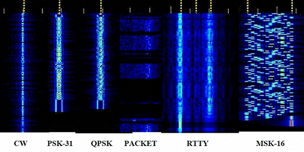
Sample traces of a few digital mode transmissions as received and captured on a typical waterfall display.
The other second generation text mode digital radios that actively used FEC schemes having varying degrees of complexities came into existence. Some of the modes are Olivia, Contestia, Thor, Throb, DominoEX, MT63, QPSK, QAM, various M-ary modes, ROS, etc. These modes used FEC with Cyclic Redundancy Check (CRC), Viterbi decoding, etc to do away with frequent ARQ thus reducing the overall transmission time, and also were better adapted to the typical simplex radio communication method that is widely used in radio communication. There are basically two types of FEC codes. The Block code and the Convolution code. Block codes use various protocols, typical ones being the Hamming code, Reed-Solomon code (RS), and Low-Density Parity-Check code (LDPC), Turbo code, etc.
Although the FEC schemes work well under typical propagation scenarios with usual noise levels by automatically correcting a certain amount of error that might have cropped up, however, under extreme conditions, they too fail and hence might require retransmission of a complete data frame.
Essentially, all these modes used either binary or multi-tone PSK or MSK for sub-carrier modulation of the digital data stream. The number of phases and tones as well as the magnitude of shifts was different for different modes. However, one thing that was common was that they were all narrowband modes and could all be used over standard radio voice modulation channels. We will not go into the merits, demerits, or structure of these codes here but will cover them in a separate set of articles under the section on Digital Modulation Fundamentals.
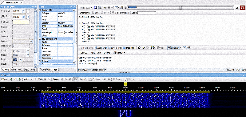
A typical digital data mode signal processing software for multi-mode encoding and decoding. The software runs on a PC that is interfaced to a radio transceiver.
The latest modes may be classified as the third generation text mode digital radio communication. Some of these modes have taken amateur radio by storm in recent years. They have the remarkable ability to negotiate extremely noisy propagation environments and also the ability to work over a very narrow bandwidth. These and many other features coupled together, render them unmatched communication capability under very weak-signal conditions. However, they too have their unique downsides. As I said, there is no free lunch. The exceptional weak-signal communication capability under very noisy conditions comes at the cost of the very slow data transmission rate. They take a long time just to transmit a few characters of text.
Another fact about these 3rd generation digital modes that are often misconstrued needs to be mentioned here. Typically, they allow communication under very weak-signal conditions. This has made a lot of people believe that they possess magical capabilities to copy and decode signals below the noise floor at SNR as low as -20 to -25 dB or even more. This is a misconception. The negative SNR figures that we come across are because they typically specified SNR is referenced to a usual SSB transceiver detection bandwidth of 2500 Hz. However, if we were to recalculate the true SNR with reference to the very narrow detection bandwidth of the specific text mode digital radio communication in question, the actual SNR will always be found to be positive. For more insight into this aspect, please check out my post titled Do Digital Modes like FT8 work Below Noise?
Some of the most popular third-generation Digi-modes are the JT65, FT8, JT9, etc. We may collectively call them Weak-Signal Joe Taylor (WSJT) modes as named after their creator. Due to the extremely slow transmission rates, the above-cited modes have been designed to impose several communication payload limitations. Unlike the first and second-generation modes that were designed for regular communication by transferring messages between radio stations, these modes allow no such thing. No messages can be exchanged, no discussions can be conducted, and no rag-chews can be carried out. They carry only predetermined canned information comprising of no more than 10-15 text characters that typically include the callsigns, signal report, QRA location, etc. A few other abbreviations like TNX, 73, etc can be also be accommodated in the transmission payload. The number of characters in a transmission round is made so restricted to ensure that it does not take forever to complete the transmission. Despite, the message payload limitations, each round of transmission may take as long as 15-60 seconds to go through depending on which of these modes is used. A full QSO that exchanges nothing else but the bare bones typically take from 2-6 minutes to complete.
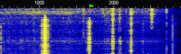
A waterfall display of a modern text-mode digital radio communication software displaying multiple closely spaced ongoing QSO within the baseband bandwidth of a 2.5 KHz SSB radiotelephony channel.
In all fairness to the creators of these modes, the WSJT modes were originally conceived for other purposes. The first of these, the JT65 was made primarily to allow easier Earth-Moon-Earth (EME) passive reflection-based radio communication. It was a great step forward and Joe Taylor (K1JT) created a marvel of technology. He applied his brilliance to create cutting-edge algorithms to process signals that distorted badly while propagating over a very high-loss and hostile EME communication circuit with various time spreads, frequency spreads, libration fading, Doppler shift, ionospheric/atmospheric scintillation, etc. The JT65 could take a big battering and yet survive.
However, despite the greatness of WSJT modes, for the purpose of regular terrestrial HF communication between amateur radio stations, their usefulness is questionable.
To resolve some of the message payload limitations of typical WSJT modes like the JT65 and FT8, new protocols based on their concept are taking shape. One such third-generation text mode digital radio protocol that is showing promising prospects is JS8Call. This new mode is not limited by frame length restrictions and allows free-form text conversations and allows regular message exchange between stations. Other than this, JS8Call also features several other goodies like the Heartbeat mode, Group messaging, etc. Despite the slow data transmission rate like the FT8 that results in a long transmission time for a message to go through, JS8Call can be used for text conversation and message exchange under extremely poor propagation conditions.
As I had mentioned before that with the ongoing development of text-mode digital radio protocols, several earlier modes fell by the side to get replaced by newer and more robust modes. Some of the modes that are rarely used these days are AMTOR, PACTOR, Clover-I, Coherent BPSK, DominoF, DominoEX, etc. These have either been superseded by newer versions or pushed out by better and more robust modes. Among the popular text-mode digital radio protocols today are the evergreen RTTY, PSK31, MT63 Olivia, Contestia, Clover-II, Thor, Throb, Feld-Hellschrieber, ROS, JT65, FT8, etc. JS8Call is the new kid on the block.
Digital mode radio communication software & station setup
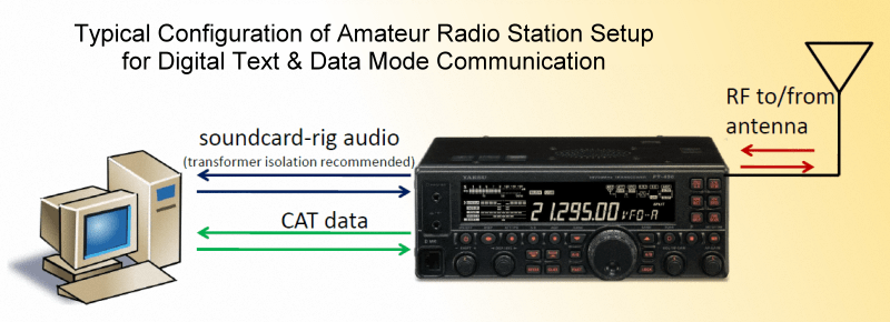
The illustration depicts a typical configuration setup of an amateur radio station operating digital modes on the HF bands using a regular SSB transceiver.
The entire focus of enabling digital mode communication capability to a radio station lies entirely in pre-processing of the audio baseband signal input to the transceiver. During both transmit and receive, the AF baseband sub-carrier modulation or demodulation for encoding or decoding can hence all be done outside the transceiver. This is the typical digital modulation paradigm that is usually adopted for amateur radio digital communication. In other words, external means of pre/post-processing need to be done elsewhere outside the typical transceiver hardware.
In view of the above, the simplest way is to use a PC connected through an audio interface cable to the transceiver. The PC runs suitable software to generate the sub-carrier AF tone that is modulated by the digital data stream (typically coming from the PC keyboard) to do sub-carrier modulation in accordance built-in algorithms that conform to the respective protocols of selected digital modulation modes. A variety of freely available software has been developed to the needful.
Initially, in the early days of digital modulation, various single-mode software that was dedicated to one particular mode was in vogue. The ones that come to mind are Digipan, WinPSK, MMTTY, etc. Gradually, software that could process more than one Digi-mode came into being. It started with HamScope and gradually evolved into more powerful and flexible multi-mode software.
Currently, there is a fairly large selection of good text-mode digital radio communication software available to radio amateurs. These include MultiPSK, MixW (paid), DM780 (HRD suite), FLdigi, etc. Of the lot, FLdigi is certainly the most popular software among the amateur radio community.
The third-generation text mode digital radio protocols are typically not supported by the above-cited software. They require separate software.
MultiPSK Software
This is one of the oldest multimode digital signal processing software. It is quite feature-rich, however, its screen interface and layout are perhaps not as good as one might have desired. MultiPSK gives a cluttered appearance and many operators often find it confusing and difficult to use.Having said that, MultiPSK which is available both as a free and a paid version is capable of encoding and decoding perhaps the largest variety of text-mode digital radio protocols in a single piece of software.
Some of the modes it supports including numerous mode variants are PSK, MT63, CHIP, DigiSSTV, CW, CCW, QRSS, Packet and APRS, Amtor (FEC), Navtex, ASCII, RTTY, Lentus, Pactor (FEC), DominoF, DominoEX, Throb, ThrobX, MFSK, PAX/PAX2, JT65, Olivia, Hellschreiber, ALE, ALE400, FAX, SSTV, Sitor, GMDSS, 1382, ACARS, DGPS, Synop, SELCAL, Amtor ARQ, etc.
MultiPSK also features a built-in logging program with the ability to interface to amateur radio rigs. Though the logging program interface is also rather shabby, it has the ability to export the log in ADIF format for viewing in other logbook software with a better interface.
MixW Software
MixW is a good text-mode digital radio software that is maintained and supported by the makers of RigExpert who offer a set of frontline antenna analyzers. MixW is currently a paid software that comes with a free trial period. The software features an integral logbook that supports a radio rig interface to capture the frequency, etc. It also has an inbuilt DX spot cluster client to help find digital mode activities on the bands.MixW is very stable and supports a number of modes and their variations including PSK, RTTY, Packet, Pactor (FEC Only), Amtor (FEC Only), MFSK, Throb, MT63, Hellschreiber, FAX, and SSTV. Other modes can be added by downloading a DLL file for that mode. It offers additional flexibility by supporting user-created macros like most other text-mode digital radio communication software.
DM-780 (Ham Radio Deluxe) Software
The DM-780 is a part of a comprehensive radio communication software suite called Ham Radio Deluxe (HRD). Though DM-780 may be run as a standalone application, if run through the HRD suite it offers several other features including PC screen radio rig interface, rig control, antenna rotation control, satellite tracking, logbook, DX cluster, etc. DM-780 is the digital mode encoding and decoding potion of the software bundle. The screen interface of DM-780 is also nice and intuitive. However, this software is not free.DM-780 provides support for most of the popular text-mode digital radio protocols. It supports the following digital modes and their respective variations: RTTY, PSK, Contestia, CW DominoEX, Hellschreiber, MFSK, MT63, Olivia, Thor, Throb and even SSTV. It does an excellent job with all these modes including CW. Although the software-generated text-to-CW works best with software CW decoders, the DM-780 fare reasonably well at decoding even with hand-keyed CW transmissions.
FLdigi software
FLdigi is by far the most popular text-mode digital radio software as of date. It features an intuitive and user-friendly interface offering ease of use. Like all the PC-based digital mode software, FLdigi too is interfaced with the transceiver via the PC sound-card and an audio interface cable. It supports features like rig control and frequency/node data interface and uses interface software like HamLib or RigCAT to perform rig control functions. FLdigi features an integral logbook with an interface to QRZ.com to collect additional information about the logged-in station. It also supports SDIF protocol with import and export functions.The digital modes and their variants that FLDigi supports include CW (modulated), Contesia, DominoEX, Hellschreiber, MFSK, MT63, Olivia, PSK, RTTY, Thor, Throb, WEFAX, etc. FLdigi is free software.
WSJT-X Software Suite
As I had mentioned earlier, the third generation type text mode digital radio applications require their own software. None of the above-cited software that supports most of the regular digital modes supports any of the WSJT modes. At the time of writing, the software available to encode and decode all WSJT modes is WSJT-X. This is free software and can handle several digital communication modes like JT65, FT4, JT9, QRA64, MSK144, FT8, including beacon modes WSPR.WSJT-X suite also has a built-in feature to log QSO. Furthermore, since modes like JT65 are often extensively used for EME Moonbounce contacts, the WSJT-X suite also provides a ready reference to astronomical data with the Doppler tracking feature.
JS8Call Software
JS8Call is a variant of the popular FT8 mode. However, unlike the FT8, JS8Call is far less restrictive because it is a conversational free-form text communication mode. JS8Call has all the weak-signal communication capabilities of FT8 but on the upside it allows more meaningful two-way QSO to be conducted between operators. Unlike FT8, JS8Call can exchange short operator formatted messages.Since JS8Call has not been developed by the creators of FT8, the WSJT-X software suite to which FT8 belongs does not support the JS8Call mode. Another separate software that is available for free download from the official website of JS8Call has to be used. The JS8Call software interface is quite similar to that of WSJT-X. Those who are familiar with one will find it easy to use the other one.
JS8Call software suite is available in different versions to run on various OS platforms like Windows, Linux, macOS, etc including a version that runs on Raspberry PI.
Basic concept of interfacing the radio rig to a PC
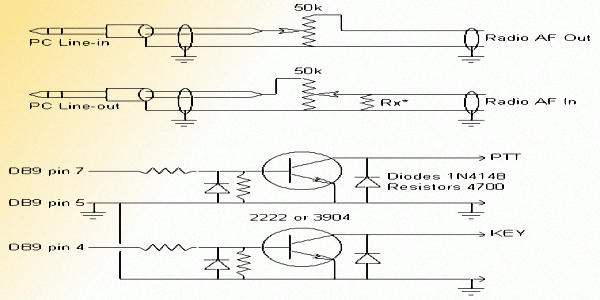
The basic concept of interfacing the PC to the radio rig using a simple cable arrangement to connect the 2-way audio input and output. An additional interface is provided to drive the PTT and the CW key input of the transceiver from the digital mode software.
The above objectives are achieved by using an interface cable between the transceiver and the PC. The transceiver side audio interfacing would need to be done at its microphone input and the speaker (headphone) output, whereas at the PC end, the corresponding connections need to be made to an external speaker and the microphone terminal points. At the PC end, the commonly found 3.5mm mini-jacks may be used. Alternatively, an external USB sound-card plugin may also be used. Whatever be the choice, the principle remains the same.
The transmit-receive cycle during the digital mode QSO may be handled by the PTT activation through the interface cable. To do this, the text mode digital radio software would need to trigger the cable interface. The separate PTT line method needs to set the logic state of a PC output interface pin. Earlier a typical desktop PC or even a laptop PC provided an RS232 serial peripheral interface. It was pretty simple to designate a specific serial port pin in software to function as the PTT output. A cable connection leading from this pin was used to trigger the PTT on the transceiver.
However, the modern PC rarely provides a physical RS232 serial port interface terminal. Therefore, we now need to use the USB port. The problem is that invariable none of the digital mode PC software nor the transceiver support direct USB interfacing. Hence, we circumvent this problem by using an external USB-to-Serial port interface hardware that creates a virtual serial port within the PC. The text-mode digital radio software running on the PC is thereafter configured to interface with this virtual serial port. The USB-Serial external hardware interface is very low cost, simple, and easily available. These are available in either the form of a USB dongle, a USB cable, or an add-on board. Once we have the USB-Serial interface in place and correctly configured it behaves identically to a normal serial port. Hence, PTT activation of the transceiver becomes feasible.
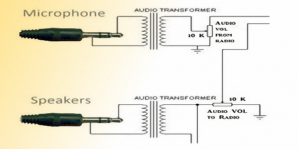
For additional safety and enhanced performance, isolation transformers are recommended on each of the audio lines between the PC and the transceiver.
For VOX-based PTT, the digital sub-carrier when produced is detected and is used to activate the PTT line on the transceiver. This is easily achieved using a small circuit comprising of a couple of small signal diodes, resistors, capacitors, and a transistor. For better results, small switching delay is often introduced using a simple addition of a low-cost IC like the NE555.
Irrespective of whether it is a direct, or a VOX-based PTT arrangement, electrically isolating the PC side and the transceiver side of the circuit is advisable for safety. A simple optoisolator in the PTT drive circuit is all that is needed. Similarly, the two-way AF lines connecting the AF input and output of the PC and the transceiver should also be electrically isolated by the use of miniature AF isolation transformers. A PC to transceiver interface arrangement that takes of all these factors works best.
Anyone who either buys a readymade interface cable or fabricates it must ensure that both the TX and RX audio lines of the cable are duly isolated with 1:1 isolated winding type AF transformers. Such transformers are typically designed for 600Ω impedance and are quite small in size. Those with transformer winding skills may wind their own AF isolation transformers while others can buy them easily available items. Similarly, low-cost optoisolators are also readily available. All signaling and data switching lines should be optoisolated. The PTT or the CW keying line falls in this category.
Identification methods and protocols for modern digital radio signals
One of the common questions that one might expect at this stage is how do we identify the digital communication mode being used when one encounters the signal on a receiver? There are so many different types of text-mode digital radio transmissions happening on the bands. How does one decode them unless one knows what the specific mode is? There are several ways of doing this. Let us examine some of the common methods used on amateur radio.
The traditional method that has been in vogue since the very beginning of amateur radio digital mode communication is for the transmitting station to make a short CW transmission announcing the mode prior to commencing the digital transmission. The receiving operator uses the CW preamble to identify the incoming digital mode signal. Thereafter, the receiving station would switch to the mode specified in the CW preamble and continue to conduct the digital QSO. This is quite a straightforward and foolproof method. It requires no additional complexity in the decoding hardware or in the software.
In modern days, however, matters have been further simplified through various forms of automation and other means of mode identification. Two of the most frequently used methods are the Reed-Solomon Identifier (RSID) and the Video ID on waterfall. The first one is an automatic software-based identification protocol whereas the second one is a manual ID method which makes life easy for a large breed of contemporary radio amateurs who are regrettably unable to copy CW.
Reed-solomon Identifier (RSID) is transmitted as a preamble to a digital mode data transmission. For RSID based mode detection and control to work, both the TX and the RX stations must have RSID encoding and decoding capabilities. Given a compatible digital mode software that supports RSID, it results in a fair amount of automation. RSID sending and decoding are background automatic process that is carried out without operator intervention.
Once an RSID preamble is detected and decoded at the receiver end, it not only allows the receiving side software to automatically switch over to the appropriate mode but also helps in homing on the exact transmission frequency of the sub-carrier to an accuracy of up to 2.7Hz. The RSID protocol features an inbuilt FEC error correction and is fairly robust with the ability to automatically correct several errors during transmission. Although it is possible, the occurrence of false RSID mode reporting is pretty rare.

An illustration of how a Video ID that is prepended to start of a digital transmission would appear on the waterfall display at the receiver end. The video ID may contain either or both the TX station callsign and the name of the digital mode.
To understand the above-mentioned limitation, we need to take a quick look at how the RSID is structured… The RSID signal is transmitted in 1.4 seconds and has a bandwidth of 172 Hz. Detection of the RSID signal is possible down to an SNR of about -16 dB. The RSID sensitivity is better or equal to many popular digital modes like RTTY, PSK31, Olivia, MT63, etc. Hence, RSID signaling works well with these modes. However, the more sensitive modes that can work well under weaker signal conditions with lower SNR would often result in the failure of RSID mode identification. Some examples of these modes are PSK10, PSKAM10, THROB, THROBX, JT65, FT4, JT9, FT8, JS8Call, etc. These modes that could work under lower signal strength conditions may function adequately with very weak signals but the signal level may be inadequate to decode the RSID preamble at those levels. When the signal is stranger then RSID works with these modes, however, under extreme conditions, RSID might fail.
Video ID on waterfall is another method often used to identify the digital transmission mode. Although this method is better suited for relatively broader baseband type digital modes that occupy a wider space on a typical waterfall window of a text-mode digital radio software, they may also be used to identify narrower modes like PSK31 also. Just prior to the commencement of digital sub-carrier transmission, a visual pattern of pixels to display on the waterfall is transmitted. This would show up as a set of text characters on the progressively rolling waterfall display. Typically, a video ID preamble of this type would carry the callsign of the transmitting station as well as the name of the digital mode of the transmission that would follow.
A Video ID is quite handy for the receiving station operators who might not be competent in copying a CW preamble or to those who might like to manually select the software detection mode the RX side and do not intend to use RSID. However, if the SNR of the signal is very low at the RX, the Video ID display may not always be clearly readable. Another downside of waterfall Video ID is that it takes up extra time and hence slows down overall communication.
Amateur radio digital mode HF band preferred frequencies
Although there is no legal restriction on working HF digital modes anywhere across the available bands for amateur radio use, the amateur community has decided to designate specified frequencies on each HF band as preferred frequencies for operating these modes. This is more of a gentlemen’s agreement. The preferred frequency designations help in several ways.
Firstly, it makes it easy for operators to find the activity of their choice without the need to scan the entire band. Secondly and more importantly, since many of the digital modes work effectively under very weak-signal conditions, it often becomes difficult to hear the transmission by the ear or be able to view the trace of the signal on a typical HF transceiver’s waterfall display. Therefore, tuning on a designated HF frequency and thereafter observing the signal on the digital mode software featuring a narrowband waterfall window with an optimized narrow detection bandwidth enhances SNR and trace visibility.
Here is a table of typical HF band frequencies used for a few popular text-mode digital radio protocols. Please note that these frequencies are only indicative. There could be variations from what is listed below due to several reasons. The preferred frequencies may be different for different ITU regions (1, 2, and 3) especially for the lower frequency bands like 80m and 40m. Moreover, several of these digital modes have sub-modes that feature a different number of modulation tones, frequency shifts, and consequently the transmission bandwidths. Some of these sub-modes might use other preferred frequencies. Nevertheless, the table provides a good starting point.
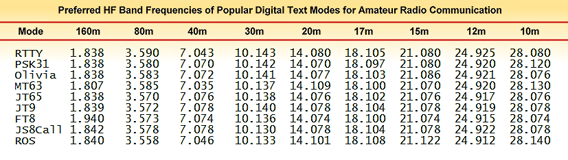
Table of preferred frequencies in common use with some of the popular text-mode digital radio communication modes for amateur radio HF bands.
Feature highlights of popular amateur radio digital modes
I will conclude this introductory article in a series on HF digital radio communication by presenting some of the salient features of a few popular amateur radio digital text communication modes.
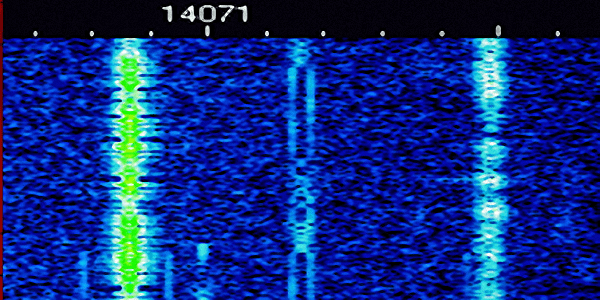
RTTY
The illustration depicts a typical RTTY signal at the receiving station's waterfall display.
RTTY uses one of the simplest and shortest character-code set. The character payload is a 5-bit code. However, the actual size of each transmitted RTTY character is 8-bit long. One bit is prepended to the 5-bit code and is called the Start Bit, while 2-bits are appended at the end and are called stop bits. RTTY is, therefore, an asynchronous mode that can pick up a transmission stream at any point and successfully decode the subsequent incoming characters. RTTY receiver does not require any kind of timing sync with the transmitter. The text data transmission rate of standard RTTY is approximately 60 WPM which corresponds to the RTTY Baud rate of 45.45. Other Baud-rate variants with different values of the shift are also occasionally used.
Since the character codes are 5-bit, they can have only 32 unique combinations. To accommodate all alphabets, numerals and punctuation marks, two code combinations out of the 32 are set aside as shift characters. The balance 30 codes can be used in combination with shift characters to allow two sets of 30 character symbols. Hence, 2x30 = 60 unique character symbols can be addressed by RTTY.
Originally, the character set was code used for cable teleprinters and was called the Baudot Code. Over time, especially with the advent of RTTY, the code set was modified, optimized, and adopted internationally by the Consultative Committee for International Telegraph and Telephone (CCITT).
PSK31
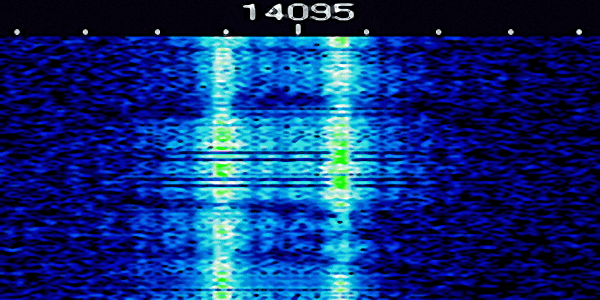
The illustration depicts a typical PSK31 signal at the receiving station's waterfall display.
Although several variants of PSK31 modes are there BPSK31, BPSK63, BPSK125, QPSK31, QPSK63, etc, and many more; perhaps the most popular mode is BPSK31 which we generally call PSK31. The effective message transmission rate of PSK31 is nearly 50 WPM. Technically, the data rate is 31.25 bauds. It requires a theoretical transmission bandwidth of 31 Hz, while in practice inter-channel spacing between two adjacent PSK31 signals can be as low as 60-100 Hz. This allows around two dozen simultaneous PSK31 QSOs to be conducted within the space required for a single SSB radiotelephony channel.
The PSK31 mode is a binary phase-shift keyed mode. It is inherently quite reliable and robust with the ability to perform great even under noisy, congested, and weak-signal HF band conditions. However, PSK31 (BPSK31) does not feature any kind of active error correction method. The PSK63, PSK125, PSK500, etc have correspondingly higher data rates, require wider bandwidths, and consequently, need stronger signals at the receiver for detection and decoding.
On the other hand, the QPSK (Quadrature Phase-Shift Keying) variants of PSK31, like the QPSK31, or QPSK63, etc have an inbuilt error correction algorithm in their protocol. The QPSK modulations with forward error correction (FEC) resort to the application of convolutional encoding and Viterbi decoding. Although the application of QPSK modulation with FEC instead of straight BPSK considerably reduces the possibility of an error during transmission, the downside of QPSK over BPSK is that the quadrature modulation imposes a -3 dB SNR penalty on the overall capability. Hence, a QPSK signal might need at least a 3 dB stronger signal at the receiver in comparison to its BPSK counterpart to be detectable.
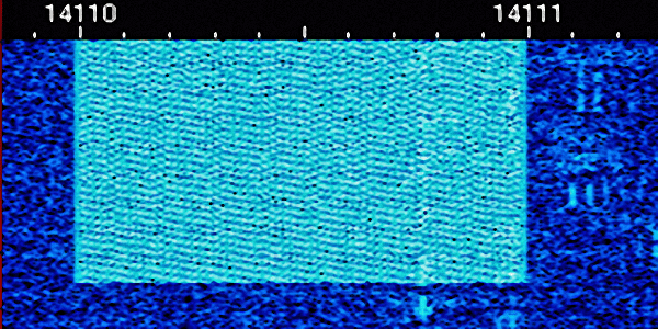
Olivia
The illustration depicts a typical Olivia signal at the receiving station's waterfall display.
The default Olivia mode uses 32 MFSK tones spread over 1000 Hz bandwidth. This sub-mode is referred to as Olivia 1000/32. Olivia uses a dual-layer sub-carrier modulation scheme. Initially, during the first phase, a classic MFSK modulation is done. Thereafter, during the second layer, a Forward Error-Correcting (FEC) code based on Walsh functions is applied. The two layers (MFSK+Walsh function) of the FEC code can be treated as a two-dimensional code, where the first dimension is formed along the frequency axis by the MFSK itself while the second dimension is formed along the time axis by the Walsh functions. Olivia also applies a process of Bit Interleaving and Scrambling to randomize the symbol pattern for better results. However, let us leave it at that because going into further depth is beyond the scope of our discussion.
Various sub-modes of Olivia might employ tones ranging from 2, 4, 8, 16, 32, 64, 128, or 256. The deviation bandwidth may also be set at 125, 250, 500, 1000 or 2000 Hz. This gives rise to sub-mode designations like 125/2, 250/8, 500/16, 1000/32, etc. Each of the sub-modes has its own strengths and weaknesses thus making them individually suitable under different propagation conditions.
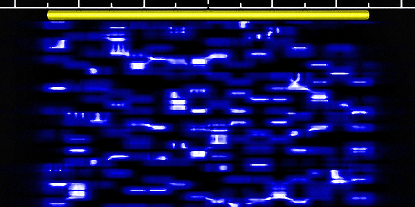
MT63
The illustration depicts a typical MT63 signal at the receiving station's waterfall display.
Each MT63 sub-modes has two further variants called Short Interleaving and Long Interleaving. The MT63 sub-mode designators are hence suffixed with either the letter (S) or (L) to specify interleaving. Therefore one would find a mode designated as MT63-1000L or MT63-1000S, and so on. The L-modes are more immune to noisy channels than the S-modes, however, this is achieved at the cost of higher transmission latency.
The 500, 1000, and 2000 Hz sub-modes have character transmission rates of 5, 10, and 20 characters per second respectively. MT63-500L mode offers the best weak-signal capability of the six variants but the message transmission time is the longest.
It offers a very fast data transmission rate and is robust and reliable. MT63 employs the FEC algorithm and is highly immune to various forms of impulse noise. It is, therefore, suitable for HF radio communication.
MT63 is very easy to synchronize on the receiver side and is capable of negotiating strong static band noise as well as intermittent noise that is typically prevalent on the HF bands. This is a relatively wider band text mode digital radio protocol that occupies 0.5-2 KHz. MT63, unfortunately, cannot easily coexist with other overlapping transmissions within the passband and would usually cause unacceptable QRM to the other partially overlapping passband signals.
WSJT modes and JS8Call
All the the WSJT modes like JT65, JT65A, JT65B, JT6M, JT9, QRA64, MSK144 (deprecated FSK441), FT8, FT4, and also a new variant JS8Call are all a part of what I call the 3rd generation digital modes. Without going into the details of these modes that I reserve for separate dedicated articles on them, for the moment, I will simply highlight some of the unique methods used by these modes and also mention some of the cutting-edge techniques that make these modes stand apart from all other text-mode digital radio protocols that we have known so far.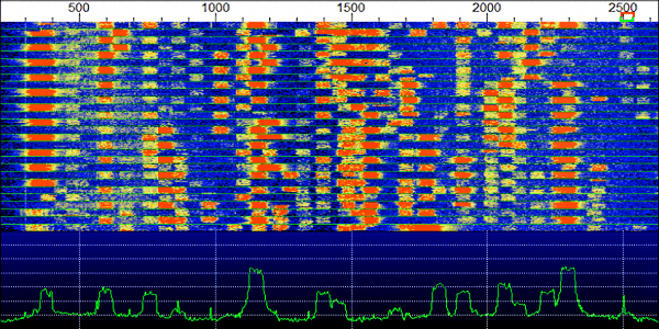
The illustration depicts a set of multiple independent FT8 QSOs in progress simultaneously within a single 2500 Hz baseband. Each FT8 QSO is space approximately 50 Hz apart. There is no adjacent channel interference noticed between stations.
Although I have mentioned several WSJT mode variants, I will briefly touch upon some of the vital aspects of JT65 and FT8. How do they work? What is the secret to the apparent magic behind their unparalleled weak-signal performance and robustness?
Firstly, they are natively all built on the basic MFSK modulation scheme. The JT65 mode which is somewhat like the parent mode of all the other WSJT modes is 64-tone or 64-ary MFSK mode. The extra 65th tone gives it the name JT65. This extra tone is used for timing and synchronization purposes. Similarly, JT9 mode uses 8 modulation tones with the 9th tone reserved for timing and sync.
However, FT8 that too uses 8-ary FSK like the JT9, it does away with the 9th tone. Therefore, FT8 requires other means of ensuring correct timing. A typical FT8 signal decoding requires the computer clocks at both the TX and RX end to be fairly closely synchronized. They must be within ±1S of one another but ±0.5S synch would be preferred.
Both the JT65 and FT8 modes are narrowband modes with very slow data transmission rates. JT65 offers better weak-signal performance of the two but requires 4x longer transmission time. A JT65 frame takes 60 seconds to transmit while FT8 takes 15 seconds to do the same. They are both restricted format non-conversational modes.
JS8Call is a variant of the popular FT8 mode. It is not a part of the WSJT software suite. JS8Call mode was heavily inspired by FT8 and has been developed as an offshoot project by Jordan Sherer (KN4CRD). The objective of JS8Call was to address some of the limitations imposed by FT8. Unlike FT8 which is a structured transmission mode that does not allow free-form text to be readily be keyed in, JS8Call, on the other hand, has been made into a conversational mode where an operator may key in any message of his choice. Not that the conversational aspect of JS8Call could be used practically for long sustained QSOs because of the slow transmission rate limitations identical to FT8, yet this feature is a welcome step.
The answer is that they employ techniques that no earlier digital mode ever did. Needless to say, the finest and most thoroughly thought out FEC algorithms have been used in WSJT modes to ensure recovery of data errors on the fly as far as possible but there are a few other unique aspects of WSJT modes that make them outstanding.
One of these other reasons is that despite the fact that the transmission bandwidth as per the MFSK schemes adopted might not be extremely narrow, the detection bandwidth of these modes typically corresponding to the symbol bandwidth turn out to be far narrower. Consequently, the noise bandwidth of these modes is very narrow resulting in the enhancement of SNR that allows reliable operation under very weak-signal conditions. For instance, the transmission bandwidth of FT8 is around 50 Hz while the detection (noise) bandwidth is only 6.25 Hz. In the case of JT65, the transmission bandwidth is as much as 178 Hz and the detection bandwidth is only 2.7 Hz This is achieved by applying aggressive noise processing and reduction algorithms but also by the application of digital adaptive filter schemes.
Another outstanding and unique feature that is found in modes like the FT8 is the implementation of Costas Arrays. FT8 encodes three Costas Arrays, one at the start, one in the middle, and one at the end of each transmission to help receiver end software identify and decode the message payload under adverse conditions. FT8 uses 7x7 Costas arrays, that was originally developed to provide improved SONAR and RADAR pings by tagging each transmission with unambiguous combinations of frequency hops and time intervals.
Let me conclude this article by saying that text and data mode digital radio communication has developed over the past few decades in leaps and bounds. These modes and the newer modes that are in the offing are opening up new vistas in the world of amateur radio communications.


(22 votes, Rating: 5.00) - Please vote the article with your valuable star rating. Thanks! Basu (VU2NSB)


SSN SSNf(10.7) – Real-time Solar Data