Cubical Quad antennas and Delta Loops
In this article, we will examine the Cubical Quad or Delta Loop geometric structure as antennas. The common term Cubical Quad will be used in general for both type of loop structures. However, specific references to Delta Loop will only be made when it warrants a distinction on account of a unique characteristic or feature.
Cubical Quad and Delta Loop Geometry

Typical geometry of Cubical Quad loop and Delta Loop
A typical Cubical Quad is usually oriented either as a square loop with two arms parallel to the ground while the other two are vertically oriented. The other common method is to rotate the loop by 45° on its axis so that it resembles a diamond shape. One diagonal of the loop is now parallel to the horizontal surface while the other is perpendicular. Such a Cubical Quad is commonly known as a diamond oriented Cubical Quad.
Similarly, the Delta Loop may also be oriented in different ways. fundamentally, a Delta Loop is also one wavelength (1λ) loop of wire like the Cubical Quad but it is shaped like a triangle instead of a square. Ideally, a Delta Loop triangle is an equilateral triangle with the length of each arm of the triangle being equal. However, at times we find Delta Loop deployments that may have either an elongated triangle (Isosceles triangle) shape or perhaps even assume other triangular shapes. The deviation of the shape of the triangle from the typical equilateral will alter its feed-point impedance, polarization, other performance characteristics, and also its radiation lobe patterns.
Principle of operation of Cubical Quad Loops
We noted earlier that a typical Quad Loop is usually a full wavelength (1λ) wire loop. Let us initially consider a square loop oriented vertically and driven in the middle of the lower horizontal segment. A simplified explanation of how it functions is to visualize it as two electrical dipoles vertically stacked one on top of another. The lower loop horizontal segment along with the lower 1/2 of the vertical lengths on each side effectively forms a dipole. Unlike normal standalone dipoles with horizontal 1/4λ wire segments on each side of the central feed-point, this dipole may also be viewed as two 1/4λ wire segments on each side of the feed-point with only one caveat. These two hypothetical dipole segments of the Quad loop are not straight but bent upwards halfway along the lengths on each side.
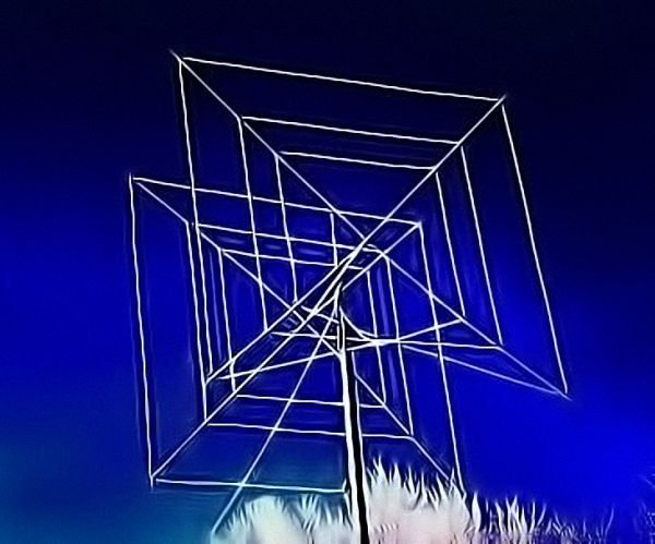
A typical 2-element Tri-band HF Cubical Quad antenna.
Now, if we were to cut our Cubical Quad loop wires precisely at the endpoints of our lower dipole (i.e. at halfway points along the vertical arms) and electrically isolate the upper section of the Cubical Quad loop, the upper section of the wire will also be another bent arm dipole which may be considered to be raised above the lower dipole with the bending of arms downwards instead of upwards. This is similar to the vertical stacking of two dipoles one above the other.
At this stage, one might say that in the case of the Quad loop, these two wire sections are joined seamlessly to form a single wire loop and are not isolated. So, how can we draw an analogy to the case of two vertically stacked dipoles? … well, we can. That’s because of the interesting nature of how current and voltage distribution occur along the length of a half-wave dipole. Read our article on Principles of Radiation for more information about voltage and current distribution on a resonant half-wave dipole.
By the very nature of the way in which RF voltage and RF current distribute across the length of a dipole at its resonant frequency, the far-end points of the dipole (which are physically open) develop maximum voltage but zero current. If we apply Ohm’s Law (Z(Ω)=V/I), we find that due to zero current (I=0) at the ends, the effective impedance at the ends has infinite magnitude. In practice, though it may not be truly infinite but will be so very high that for all practical purposes, it behaves like an open circuit point, even if the wire ends were not physically open circuit.
Therefore, even though the two dipoles (lower and upper) that we cited in our analysis above may not be physically isolated at the ends and are connected to each other to form a physical seamless wire loop, electrically (at the RF resonant frequency) they appear to be well isolated due to very high impedance at those points near the half-way mark on each vertical segment of the cubical quad loop. In other words, the very fact that those vertical segments of the loop are physically connected does not change the fact that high impedance at these points makes them behave as though they are isolated.
The Cubical Quad leverages the above principle to function the way it does. Now, since we have established that the Cubical Quad loop electrically behaves as two vertically stacked dipoles at the resonant frequency, we will take our narrative further and try to examine what it all means. Prima facie, a Cubical Quad loop at resonance, behaves akin to a pair of vertically stacked bent-arm dipole elements.
How would a vertical stack of two dipoles behave? That would depend on the phase relationship of currents flowing in the two dipoles. Under the condition of 180° phase difference, they would work like a broadside array and radiate in the plane of the dipoles (like W8JK antenna). We do not want that. However, if the current distribution on both the dipoles are in phase then the broadside radiation of the array will be perpendicular to the plane of the dipoles. This is precisely what we want in the case of a cubical Quad.
This brings us to an interesting question. If the high impedance points at the center of the vertical segments make the Quad loop behave like two dipoles, then is it possible to split the loop at these points by placing insulators? Will the structure still perform like a cubical Quad? … The answer is NO, it won’t. One may ask why? The reason is that the upper bent-arm dipole will not be driven anymore. It will have to rely on induction field coupling like a parasitic element as in a Yagi. In our article on Yagi antennas, we explained in detail how induction field coupling of this nature reverses the induced current phase by 180° on the parasitic element. The phase of current on both the dipole sections will no more be 0°, and hence the Quad loop will not radiate broadside to the plane of the loop.
The seamless wire loop with no insulators allows the lower driven dipole segment to also drive the upper dipole. Interestingly, the upper dipole is fed at both its ends by the lower dipole and the lower dipole also acts as a large T-match type impedance matching section for the upper dipole.
The seamless wire loop with no insulators allows the lower driven dipole segment to also drive the upper dipole. Interestingly, the upper dipole is fed at both its ends by the lower dipole and the lower dipole also acts as a large T-match type impedance matching section for the upper dipole.
Characteristics of a cubical Quad loop
Let us take a look at the performance characteristics of the Cubical Quad loop. Firstly, due to the vertical stacking of two dipoles one might expect the Quad loop to have approximately 2-3dB gain in comparison to a dipole. However, the gain enhancement is much less. This is primarily because the effective dipole sections of a quad loop are not straight but bent sections (only 1/4λ horizontal) thus reducing the native gain of each section compared to a full-length straight dipole. The net result is that the gain enhancement of the Cubical Quad loop is roughly 1.0-1.2dB.

Quad array – Broad azimuth and narrow elevation lobes
Thirdly, the Cubical Quad loop being a full wavelength structure has a slightly wider bandwidth than a dipole or a Yagi. The SWR bandwidth is wider which helps a larger band segment coverage.
Lastly, the Cubical Quad loop also has a more desirable radiation lobe pattern especially for terrestrial HF radio communication, and is usually a better DX performer than a dipole. In an array configuration, a Quad array would offer better DX performance than an equivalent Yagi. Why is it so? The reason is twofold. The azimuth lobe pattern width of a Cubical Quad loop would be wider on account of bent-arm dipole segments. More importantly, the elevation lobe pattern is more compressed. A Quad loop also tends to produce a slightly lower take-off angle due to the vertical stacking effect of the two effective constituent dipoles that we have been referring to. However, this to is not always true and comes into play provided the cubical Quad loop is deployed at a considerable height above ground.
The above narrative about the broadening of azimuth beamwidth while compression of elevation beamwidth is true in the case of horizontally polarized configuration. However, in the case of vertically polarized configuration achieved by shifting the feed-point, the roles of azimuth and elevation planes with regard to broadening or compression of lobes is reversed.
The net result of all the above factors is that a practical Cubical Quad loop offers about 1.0-1.2dB higher gain with a slightly wider SWR bandwidth, lower take-off angle under certain conditions, narrower elevation lobe, wider azimuth beamwidth, and at times a slightly quieter RX antenna. The main downside of the Quad loop is that it is a far larger structure which along with spreaders, etc is often mechanically less robust while also offering a much higher wind loading surface area often resulting in a structural failure in event of high wind speed storms.
The feed-point impedance of a full wavelength Quad loop is approximately 100Ω
Orientation and Polarization of Cubical Quad and Delta loops
In the case of Cubical Quad loops, the orientation of the loop generally has two distinct forms. It is either a square loop orientation with the bottom side parallel to the ground or a diamond configuration where one of the diagonals is parallel to the ground while the other diagonal is vertical.

Feed-point vs Polarization in Delta Loop
A Delta loop also behaves quite similarly. However, it has a little less gain compared to a cubical Quad loop. A Delta loop is usually oriented with one arm of the triangle parallel and the apex at the highest point or it may be set up with the apex at the bottom and the opposite leg of the triangle at the top like a horizontal wire. In either case, feeding the loop at the top or bottom produces horizontal polarization. Though feeding the loop at the top may often be more inconvenient, it certainly produces a lower take-off angle. To make the Delta loop vertically polarized all that you need to do is to shift the feed-point to a corner of the horizontal base arm of the Delta loop. This arrangement results in the lowest possible radiation take-off angle and is perhaps well suited for DX. However, please keep in mind that vertically polarized antennas are more susceptible to picking up QRM due to man-made electrical noise which may be quite a nuisance in urban areas.
Cubical Quad and Delta Loop Arrays
Before we proceed further, let me categorically dispel a popular myth that has been perpetuated over the decades about Cubical Quads and Delta Loop antennas especially amongst the amateur radio community. It is generally believed that Quad or Delta antenna arrays have much higher gain than a Yagi with an equivalent number of elements. This is quite untrue. The gain advantage of these antennas over the Yagi is very marginal at best.
Having said that, these antennas are undoubtedly great antennas in their own rights but certainly nothing better than a Yagi in terms of gain. The gains of both are similar. However, a Cubical Quad or Delta Loop array definitely has a better front-to-back (F/B) ratio than that of a similar Yagi. On a congested HF radio spectrum, this feature alone may often justify a cubical Quad. If the QRM from co-channel or adjacent channel interference from stations at the backside of the beam can be further reduced, it may certainly be worth it.


(16 votes, Rating: 4.75) - Please vote the article with your valuable star rating. Thanks! Basu (VU2NSB)


Ham Rig Reviews Coming Soon
SSN SSNf(10.7) – Real-time Solar Data