Multiband End-Fed Half-Wave EFHW Antenna
However, in the present day and age, thanks to many commercially manufactured EFHW antenna available in the market, more and more radio amateurs, especially the newcomers to HF communication are opting for this antenna despite its numerous shortcomings that can only be partially mitigated to acceptable levels by careful adjustments and tweaks that could be done by a knowledgeable and seasoned operator. A rookie operator, on the other hand, might most probably not even be aware of these shortcomings, let alone knowing ways and means of addressing them. Despite this many people take a plunge into amateur HF radio, armed with a fancy high-end transceiver on one hand, but at the same time, most of them seem to be blissfully content with an out-of-the-box commercially available EFHW wire antenna. Perhaps the reason is that the EFHW antenna is lightweight, low-cost, multiband, and therefore mouth-wateringly lucrative at first sight.
To help understand the strengths and weaknesses of the End Fed Half Wave (EFHW) antenna, in this article, I will try to present, the design attributes, characteristics, behavior, and the resulting overall performance that one might expect from an EFHW antenna. This might help several operators to make informed choices, and also avoid various pitfalls that many amateur radio operators encounter with this type of antenna, only to spend a lot of time and money later, struggling to find solutions for various performance deficiencies.
A Brief Synopsis of the Antenna Features & characteristics
In this article, I will try to cover various aspects of the End-Fed Half-Wave (EFHW) wire antenna including, its geometry, characteristics, performance parameters, the influence of the practical surrounding environment where the antenna might be deployed, as well as transmission line interfacing. In addition to all the variables that apply to an EFHW antenna, I will present some of its major shortcomings w.r.t. its geometry that leads not only to highly diverse azimuth radiation lobe patterns on different bands but also various performance issues caused by its geometrical imbalance. These factors often result in poor EMI/RFI and noise performance unless sufficient care is taken to minimize these adverse effects. Take a quick look at the summary below before we proceed further. The indicated Power Gain is TX mode is the gain that factors in the overall Radiation Efficiency of the antenna installation. RDF stands for Receive Directivity Factor and it characterizes the antenna receive performance. Radiation efficiency takes into account all structural losses and also ground reflection and absorption losses when applicable.
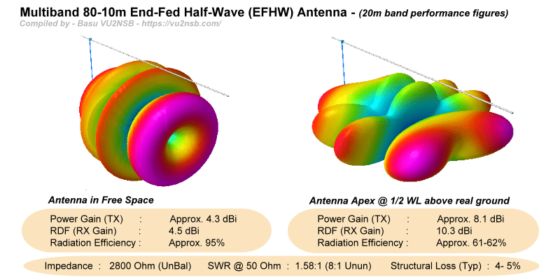
Going by the above summary, it is quite evident that an EFHW wire antenna is potentially a practical antenna that offers decent radiation efficiency and also a substantial gain if deployed carefully with adequate due diligence. Despite several positives related to the convenience of deploying an EFHW antenna, many EFHW antenna installations fail to deliver satisfactory performance. This is usually due to recklessly and thoughtlessly carried out installation and deployment.
We will try to find the reasons as to why the performance of a simple and convenient antenna like the EFHW, so often, tends to produce compromised results. We will also examine what could be done to mitigate these issues.
The answer to the above question may be given in two parts...
- PART - 1 : The EFHW antenna as a radiating and receiving element is a decent multi-band antenna with good efficiency on all bands, provided it is driven at its feed-point using a well configured and well-matched driving source. However, it has its idiosyncrasies. The radiation pattern of this antenna on most bands produces multiple lobes. The orientation of these lobes varies with the frequency band of operation thus resulting in directional inconsistencies between bands. Moreover, this antenna produces several inter-lobe nulls creating multiple band dependant shadow regions in its coverage. Radio amateurs using this antenna might remain oblivious to the presence of many active DX traffic originating from the direction of the shadow regions in the nulls.
- PART - 2 : Most EFHW antenna configurations resort to the use of broadband impedance transformers at the feed-point to attain acceptable SWR on all operational bands. This is typically a weak spot. The conjugate impedance matching arrangement of this nature is far from perfect resulting in considerable reactive currents on some of the bands. The parasitic reactances near the feed-point also vary between installations. Hence, there is no optimum single-fit solution. Each installation might require custom adjustments for the antenna to perform within acceptable norms... This condition is rarely met in typical amateur radio EFHW antenna deployments leading to compromised overall antenna system performance. The above factors often also lead to unacceptably high CMC on the coaxial cable transmission line thus rendering a rather poor antenna system.
The bottom line is that although the EFHW antenna has promising potentials, most amateur radio installations that rely on the out-of-the-box deployment of a commercially procured EFHW antenna might have many performance-related shortcomings. To make matters worse, many amateurs radio operators tend to believe that this antenna could be deployed in any way they feel and yet continue to perform well... This is a false notion... Even though one might achieve acceptable SWR on all bands, it would not necessarily imply that the antenna is performing well. The antenna's radiation efficiency, lobe patterns, gain, etc., all go for a toss if the EFHW antenna wire is deployed with random and haphazard orientations. For instance, even a standard and neat Inverted-V configuration of the EFHW wire antenna is far inferior in performance to a regular horizontal configuration, let alone other random orientations which could often end up performing quite terribly.
Read on to understand the EFHW antenna, so that one could learn how to optimize your EFHW antenna installation and avoid various performance pitfalls...
EFHW Antenna Geometry versus Center-Fed Dipole
One of the biggest technically problematic issues attributed to an EFHW antenna is its grossly imbalanced feed-point impedance leading to less than ideal transmission line behavior of the coaxial cable that runs down to the ham shack. Moreover, many of the EFHW wire antenna installations cut corners by deliberately depending on the outer braid of the coaxial cable as the antenna counterpoise. This is the worst possible thing to do as it leads to countless performance issues of the overall radio station. For a good antenna system, it is imperative to ensure that the transmission line is in no way a part of the antenna radiating system. It should be isolated from any possibility of playing a role in signal radiation. This is why a balanced antenna system based on a Dipole type configuration is by far superior in comparison to an EFHW antenna... The bottom line is that the Common-Mode Current (CMC) on your transmission line should almost be negligible if you want a truly well-performing and optimized station setup... Check out the associated illustration.
Does your station desperately need a good RF ground to behave properly?

This illustration provides a graphical view of approximate comparative difference in expected Common-Mode-Current (CMC) that could flow on the transmission line to undermine the overall performance of the antenna system. In comparison to the EFHW antenna, a simple dipole offers a far better prospect.
Does this sound like nonsense? ... Well, not really... We must understand that there are primarily three types of groundings that relate to a typical radio station. We must understand the distinction between them to follow what I am referring to.
These three types of grounds are - The electrical ground, the lightning ground, and the RF ground. The first type, the electrical ground is absolutely essential and it should be considered a necessary safety precaution to protect oneself against electrical power utility shock hazards. A good and robust electrical ground is recommended if you use electric mains powered equipment. If someone uses just a battery with no part of the station equipment connected to the electric power outlet, then you don't even need this ground.
Next, it is the grounding system to protect against lightning and other forms of nature's static discharges. Grounding elements for this do not belong within your shack. God forbid, if you have the misfortune of a lightning strike, you surely don't want the tens of kilo-amperes of lightning surge current to pass through your shack into the earth ground to eventually burn down your house. Protective grounds against lightning are always done outside the house and near the foot of the antenna installation and not within the shack. Even then, how effective is lightning ground in event of a strike is anybody's guess.
The third type, the RF ground, should usually not be required. Why should RF currents be flowing around on the rig's body, chassis, or connector's body of various equipment in your shack? ... There should be no such current and hence there should be nothing to ground. This unwanted RF current is always produced to an improperly configured antenna + feeder-line system. Eventually, due to a common-mode potential, a certain magnitude of RF current flows down along the outer braid of the coaxial cable to end up on the body surface and the chassis of your rig and other attached peripherals like the ATU, etc., to quite often make them malfunction or produce spooky behavior. So, what do you do now? ... Of course, now you need to find a way to get rid of this unwanted current. In other words, you first create all the mess yourself due to recklessness, negligence, and carelessness; now you want to try out various kinds of crazy RF grounding arrangements to mop up the mess you created... Wouldn't it be better to avoid creating the mess in the first place? Think about it.
The SWR is good, so I have a great antenna setup... Isn't it?
Nah!!! ... The low SWR obtained by you means almost nothing unless various other antenna attributes have been set up properly. Otherwise, even a perfect 1:1 SWR might not be good enough. Moreover, a lot depends on what is the cause of low SWR. Is it due to a good antenna feed-point end match or is it due to the rig-end match using an ATU? ... Among several other things, this factor also matters.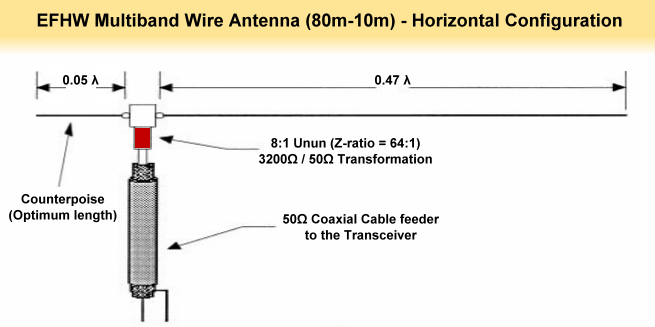
A typical schematic representation of an EFHW antenna with a short counterpoise and driven with a impedance transformer Unun.
Returning to the core discussion, why is it that a balanced antenna of the Dipole class that includes not only other wire antennas like the G5RV, W8JK, Doublet, etc; but also more complex configurations like the Yagi, Cubical Quad, etc is usually far superior in overall performance compared to an EFHW antenna or even an Off-Center Fed Dipole (OCFD)? ... The most important reason for this is that these antennas have balanced feed-point impedance w.r.t. the ground. As a consequence, a transmission line that is connected between the antenna and the transceiver in the shack tends to perform as intended without jeopardizing the overall antenna system performance. In the case of a balanced line feeder like the oper-wire ladder line or window line, the connection from the antenna is simple and straightforward. While in the case of a coaxial cable feeder, the feed-point configuration is also pretty simple where one could use a Balun for optimum results. This Balun could be either a broadband ferrite core unit or else one might use a transmission line Balun. Whatever one might choose, the result is quite effective. To further optimize the antenna system performance under practical conditions, a small common-mode Current Choke (CMC choke) installed between the Balun and the coaxial cable is a good idea.
On the other hand, in the case of a grossly unbalanced antenna like the EFHW wire antenna, configuring a satisfactory transmission line coupling to the antenna for achieving acceptable performance is far more tricky. Quite often, reduction of the CMC on a transmission line and obtaining a decent EFHW antenna performance may turn out to be mutually counteractive. Most EFHW antennas are a compromise in this respect... Not to say that one couldn't mitigate the problems, but it requires a fair understanding of various aspects of transmission line and antenna physics. Though a seasoned radio amateur might be able to tame an EFHW antenna, for an average operator, it might be beyond his field of expertise. Moreover, to achieve good results, the EFHW antenna installation would need a wire counterpoise of a reasonable length which would require some additional work and more importantly additional space, thus partially negating the generally perceived simplicity of the EFHW wire antenna configuration.
Before we move further, let me state that some people tend to casually refer to the EFHW antenna as an EFHW Dipole... This is an incorrect nomenclature. To qualify as a dipole, the wire antenna must have two balancing element sections on either side of the feed-point. Otherwise, it's not a dipole. At best, it might be classified as a horizontally configured monopole.
Typical EFHW Antenna Characteristics & Performance
Let us now take a closer look at the EFHW antenna. We will examine not only its radiation performance characteristics but also other subtle characteristics that influence transmission line behavior, thereby impacting the overall radio station performance.
To begin with, we will focus on some of the positive attributes of an End-Fed Half Wave (EFHW) wire antenna. Other than being light-weight and easy to install, it is truly a multi-band resonant antenna for the HF amateur radio bands. Technically, almost all (reasonably long) random wire lengths could perform as multi-band antennas, the emphasis here is on the word Resonant. As a consequence of multi-band resonance, the antenna presents an acceptably low SWR on all the frequency bands that it is designed to serve.
Whether it is an EFHW wire or a typical balanced dipole, or an OCFD wire antenna, the multi-band resonance becomes possible in the case of amateur radio due to the nature of frequency band allocation for amateur radio service. All the HF radio bands allocated to amateur radio are typically more-or-less closely related harmonically so that the half-wavelength on the lowest allocated frequency band produces integral multiples of half wavelengths for all other higher frequency HF bands... Does the above statement sound confusing? Don't fret... Let me explain.
As an example, let us take a wire that is half wavelength (1/2λ) on (3.5 MHz) 80m band. This length will be equal to 2 x 1/2λ on (7 MHz) 40m... 3 x 1/2λ on (10.5 MHz) 30m... 4 x 1/2λ on (14 MHz) 20m... 5 x 1/2λ on (17.5 MHz) 17m... 6 x 1/2λ on (21 MHz) 15m... 7 x 1/2λ on (24.5 MHz) 12m... 8 x 1/2λ on (28 MHz) 10m...

This animated illustration shows the harmonically related current conditions that exist on the EFHW antenna wire on various HF bands. This graphical depiction makes it easier to visualize the current and impedance correlation between bands.
The above example depicts how a single length of wire that is cut to 1/2λ resonance on the 80m band would essentially resonate harmonically on practically all the allocated amateur radio HF bands. Hence, this length of wire is a multi-band HF wire antenna that would resonate fairly well to produce good and repeatable feed-point impedance and stable SWR on all bands... Now, one might ask, if this is so simple then why doesn't a regular center-fed 80m band dipole work as a good low SWR antenna on all HF bands?
The answer to the above question lies in the fact that a half-wave dipole being center-fed splits the wire length into two smaller 1/4λ sections. Being center-fed, it is driven a the highest current and lowest voltage central feed-point. For an 80m dipole, this feed-point condition to achieve good SWR will only be possible on 30m, 17m, 12m, apart from the 80m band. This antenna is not very useful because for most radio amateurs the 40m, 20m, 15m, and 10m capability is more important... However, a center-fed dipole for the 40m band would typically resonate on the 15m band also. This feature is often used by amateur station operators.
Even though the 80m half-wavelength wire effectively resonates (harmonically) on all HF bands as we examined above, the center-fed dipole configuration doesn't appear to be a practical option to produce acceptably consistent feed-point impedance (and consequently low SWR) on all bands. We need a different feed-point arrangement to achieve an all HF band SWR consistency. An end-fed arrangement makes it practical to achieve this objective. However, it leads to few other problems... Firstly, the feed-point impedance attainable near one end of the wire is very high. This may be surmounted by the use of a broadband RF impedance transformer. This is precisely what is done in the case of the EFHW wire antenna.
The other more serious issue happens to be the fact that by its very nature, a transmission line is not meant to drive a load that does not provide a suitable return current path. The EFHW antenna creates a situation that is quite similar to the above. An EFHW antenna is like a load connected to one end of the two-wire transmission line. The other conductor of the transmission line practically encounters an open circuit, since there is no antenna element on the other side. This creates a peculiar situation. Practically all the current flow on one wire of the transmission line while the other wire carries very little counter-balancing current. A transmission line should be a part of a closed circuit where both the conductors of the line ought to conduct currents of equal magnitude but opposite polarity... In the case of an EFHW antenna, this principle is grossly violated.
This current imbalance in the transmission line conductors leads to what is known as Common-Mode Current (CMC). CMC is equal to the difference in currents flowing through the two conductors. This CMC must flow into something and terminate somewhere. Unless there is a reasonable length of counterpoise wire at the other end of the EFHW antenna feed-point, the CMC would typically have no option but to flow into the ground via the outer braid of the coaxial cable. As a consequence, at first, the CMC (which is RF current) enters the ham shack along the coax braid, thereby putting all connected equipment in the shack, like the transceiver, ATU, etc., at elevated RF potential. Thereafter, people try to flush the CMC by employing a variety of radio station grounding (earthing) techniques. When a physical RF ground is not practical, operators try to use an artificial ground which is effectively nothing but a simulation of an open-ended 1/4λ transmission line (or a lumped-circuit equivalent). This, in turn, electrically simulates a low-impedance ground equivalent at the shack-end.
The above-cited desperate measures might work to a limited extent in mitigating the CMC RF problem but it is never really optimum. A proper and a good length of a counterpoise wire at the EFHW antenna could be a far better alternative than trying to get rid of the excessive CMC by hit-and-miss RF grounding arrangements. At this stage, some might ask, how about a good and aggressive CMC choking scheme near the antenna-end of the coaxial cable using ferrite beads and toroid chokes but without using a counterpoise wire? ... Well! that will substantially destroy your EFHW antenna performance. Before the application of CMC chokes, at least your antenna was completing its own basic electrical circuit requirement by using the coaxial cable braid. Now, that you have attempted to choke the CMC RF on the cable without providing an alternate path, you might have technically rendered the EFHW antenna incomplete and broken by either ensuring that adequate RF power transfer for radiation may not occur or else, by creating a dangerous situation due to very high RF voltage developing across the CMC choking elements...
As I mentioned earlier, a properly balanced antenna system should produce negligible CMC, and hence an amateur radio station using such an antenna system would normally never need any kind of RF ground... However, those using EFHW antennas (or similar ones) are less fortunate and therefore usually struggle to control and manage RF current issues in the shack.
To sum up once again, the above described CMC (typically prevalent in EFHW installations) is a part of the antenna current. This might be a fairly high magnitude RF that flows down the transmission line cable into the ham shack and eventually into the transceiver and other equipment in the shack. Had the antenna been a balanced antenna like a dipole then currents of opposite direction and equal magnitude would have flown through the two conductors of the transmission line, thus effectively producing none or negligible CMC to worry about. Alas! ... Unfortunately, that's not the case with EFHW antennas.
The above factor is solely responsible for grossly destroying the performance capabilities of the antenna and rendering the EFHW wire antenna rather mediocre at best unless of course, appropriate measures are taken on a case-to-case basis while installing the antenna. I will address some of these measures in the next section of this article.
What are the consequences of the CMC on the antenna performance? ... They are pretty nasty from the perspective of a serious radio communication setup that might be intended to transmit at regular power levels. Unless it is a QRP station, an excessive and unacceptable magnitude of EMI/RFI in the neighborhood due to the unwanted transmission line radiation occurs due to high CMC. Under some conditions, the RF current (CMC) that flows down the transmission line into the shack could result in malfunctioning of equipment including the transceiver itself, when the PTT is pressed. In more severe cases, CMC might permanently damage equipment, cause electric shocks, and might even result in RF burns. On the other hand, while receiving, CMC on transmission line results in picking up all kinds of extraneous noise thus compromising the Signal-to-Noise Ratio (SNR) of the desired signal. The weak signal reception capabilities of the radio station are drastically impaired... The net result is that such a situation may potentially render the radio communication installation practically useless for quality communication work.
Despite the above factors, many amateur radio operators continue to use poorly setup EFHW antennas and carry on living with these issues, blissfully unaware of what they are missing. Most of the time, they are unable to hear or work a large number of weak and moderate strength DX stations from around the world that are present and active on the HF bands at that time... They think that the bands are closed and blame the pathetic situation they experience primarily on the Solar Cycle, SSN, and other aspects of mother nature... Believe me, that's not usually the truth.
Influence on Performance due to Deployment Environment
As in the case of all kinds of multi-band wire antennas based on multiple fractional half-cycle resonance methods, the EFHW antenna also features peculiar variation in azimuthal radiation lobe patterns when switched from one band to another. This is a common trait shared by other multi-band wire antennas like the G5RV, Windom, Off-Center Fed Dipole (OCFD), Doublet (Double Zepp), T2FD/T3FD antennas, etc. At the higher frequency bands due to multiple half-wave resonances along the wire length, the azimuth lobe no more remains a well-defined, broad-side oriented, figure-of-8 pattern unlike a regular 1/2λ dipole wire antenna. The change in the direction of the primary radiation lobes on the higher frequency bands shifts drastically with a tendency to gradually align along the direction of the wire. The typical bi-directional broadside lobes as expected from a dipole split up and begin to produce four (or more) diverging lobes pointing in different directions... This is what also happens in the case of an EFHW antenna.
On the lowest frequency band where the length of the EFHW wire is equal to 1/2λ for that band, the azimuth pattern remains identical to that of a dipole, however. This pattern holds over an octave (2 times) of frequencies beyond which the lobe splitting begins to occur.
In other words, for an EFHW wire antenna having a length of 1/2λ on the 80m band will have a proper dipole-like pattern 40m also. As we switch beyond this into 30m, 20m, 17m, and so on, the azimuth lobes split and tilt in the wire direction. On some of the higher frequency bands (which are essentially DX bands), the EFHW wire antenna might produce deep nulls in the broadside direction of the wire... This is contrary to the popular expectation that might catch someone off-guard unless one is conversant with this phenomenon.
Hence a multi-band EFHW antenna if installed with an orientation along a preferred direction that a person usually does while deploying a normal dipole might be in for a rather unpleasant surprise. For instance, a mono-band 20m dipole oriented in a particular way might have resulted in very strong signals from the preferred DX directions, but an 80-10m multi-band EFHW antenna deployed along the same orientation would most like fail quite miserably for DX on the 20m band, even though 40m DX from that direction might still come in strong.
However, the saving grace is that many of these EFHW antenna deployments of amateur radio operators are rather mediocre and are installed at sub-optimal heights above ground level. Due to the relatively close proximity to the ground and other surrounding objects like buildings, etc., the azimuth radiation lobe patterns get quite rounded with lesser null depths. The situation arising out of such deployment environments greatly mitigates the lobe direction problems that one might have faced if the antenna had been nicely and meticulously installed at a good height above the ground level. This is why most amateur radio operators get away with the inter-lobe null problems but at the same time end up with an antenna having extremely poor low takeoff angle DX performance.
Let us examine the elevation and azimuth lobe patterns on several bands of a typical EFHW antenna that is deployed at a fairly decent height of 40 ft. AGL. Check out the illustration below to get a better insight into what we have been discussing above. Observe the multiple sharp lobes especially on the mid and higher frequency bands that are usually best suited for HF DX. You might also notice that the radiating lobes point in different directions which are not consistent and change from band to band. In other words, a DX station may appear to be strong on one band when the propagation opening exists, while the same station might never be heard on another band despite good propagation opening at another time. This would be because the direction of incoming DX signal might fall within the inter-lobe null on the second band, whereas on the first band the signal fell on an antenna lobe.
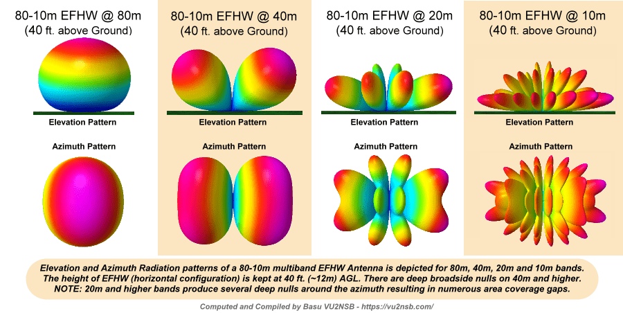
The above illustration displays a typical set of Azimuth and Elevation sections of the radiation patterns that one might expect from a horizontally configured EFHW Wire Antenna deployed at an average height of 40 ft. above ground level (AGL).
Construction Variables and Transmission Line Interface
Before we take up the steps and measures that could positively influence the overall performance of the EFHW antenna and might even make it behave quite nicely across all HF bands, we need to appreciate the fact that essentially this antenna is meant for QRP work. An EFHW antenna is very practical and convenient for field use and temporary installations. For instance, it is very easy to sling the wire over a tree branch and set it up into an Inverted-V configuration. Then feed it near one end that is conveniently close to the ground... And voila! ... There we have a multiband HF antenna up and running in a jiffy. However, for permanent installations and non-QRP power levels, I would still suggest, find a better alternative.
Having said that, let us see what we could now do to make the EFHW wire antenna perform gracefully enough without giving us too many heart-aches. At this stage, we must recognize without ambiguity the fact that the EFHW antenna is a bit finicky and a rather unstable antenna from the point of performance replication between different installation sites. Unlike many other types of antennas that can easily be deployed out of the box and expected to perform as specified, the EFHW antenna might usually require custom tweaks at every installation for it to be able to replicate performance behavior.
One of the prominent variables is the net vector-sum of the RF current distribution flowing from the transmitter through the transmission line into the antenna's feed-point node. This balance could vary from one installation to another. Some installations might need to use a physical ground while others might need a short counterpoise element to balance out the current flows. Others, of course, might typically end up with unacceptably large CMC on the coaxial cable.
Another reason why the replication of performance at different installation sites becomes difficult is due to the high feed-point impedance of the EFHW wire antenna. The higher feed-point impedance means the higher is the susceptibility to variations in parasitic reactances around the antenna environment, especially near its feed-point. This gets further compounded due to the end-fed nature of the configuration which usually places the feed-point near a physical mounting structure thus increasing the chances of more variations in parasitic reactances. For instance, additional capacitive coupling to a metal mast might provide a partial alternate path for the feed-point node balancing current to flow, thus, in turn, altering the electrical RF behavior of the installation.
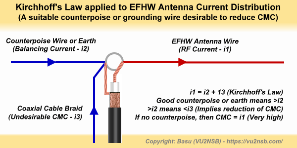
application of Kirchhoff's current Law on a typical EFHW antenna configuration. The vector sum total of all currents flowing on various physical antenna wires plus other currents like CMC on the transmission line or parasitic induced currents on masts or nearby objects must always be equal to zero.
Because of the above, whatever magnitude of RF current (radiation + loss) would need to flow into our antenna element, an equal magnitude but opposite phase (direction) current must also flow into the antenna feed-point... But how will this happen? ... In the case of a balanced dipole, two equal length element sections are connected to the feed-point node. Hence, RF current flows in from one direction from one element section and flows out in the other direction into the other half of the dipole section. Thus, the net current at the dipole feed-point is zero, and Kirchhoff's law is sustained.
Fair enough, but how can the above criteria be fulfilled in the case of an EFHW antenna? After all, the entire wire element is on one side of the feed-point which happens to be at the end. So, where will the counter-balancing RF current to fulfill the Kirchhoff's law conditions come from?
This is precisely the issue. A counter-balancing Kirchhoff's current must somehow be forced into the feed-point node for the EFHW antenna to work. It doesn't matter if the counter-balancing current comes from one source or multiple sources, as long as their sum total is equal in magnitude and opposite in phase to the current flowing through the main antenna wire.
One simple way is to run a ground wire into the soil (earth). This would be the counterpoise end of the antenna feed-point. The earth acts as the current return path. The other popular method is to connect a piece of wire of reasonable length to the other end at the feed-point. Both these methods produce the counter-balancing current required for the antenna to function. However, the problem is that in every case the impedance presented by the counter-balancing element is invariably different from the impedance produced by the radiating element. This results in unequal current magnitudes and hence it becomes practically impossible to completely eliminate the CMC on the transmission line. Proper ground return or a designated length of counterpoise wire would certainly reduce CMC on the cable but it would never eliminate it... All EFHW users have to live with this malaise.
Optimum Counterpoise length and Coupling Transformer
So far, in the article, we have discussed at length various important aspects that influence the performance of an EFHW antenna. One of these factors is the counterpoise. Some people might tell you that you don't need a counterpoise. Don't listen to such nonsense... Although the counterpoise wire need not be very long, a no counterpoise scenario is a sure-shot recipe for disastrous performance.The optimum length of the counterpoise wire, as determined by extensive experimentation and mathematical analysis turns out to be approximately 0.05λ of the lowest frequency band to be covered by the antenna. For instance, in the case of a typical 80m-10m coverage EFHW antenna, the length of the counterpoise must be around 0.05λ of 80m. This short length of counterpoise wire is vital to improve the overall performance and more importantly it allows us to aggressively throttle the CMC on the coaxial cable by judicious use of a set of RF current chokes.
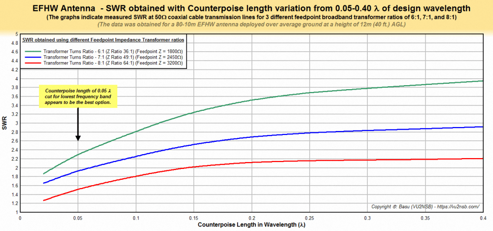
A graphical presentation of the mathematical analysis of EFHW antenna SWR variations on account of variations in counterpoise length as well as the Unun impedance transformer at the feed-point.
Take a look at the above illustration. We notice a few very interesting factors. The graph shows the SWR-related behavior of an EFHW antenna with different lengths of counterpoise wire and also shows the effect of various impedance transformation ratios of the feed-point side Unun. Letting the counterpoise wire length to be around 0.05λ of the lowest frequency band (80m) serves a useful purpose for the overall performance of the antenna on all other HF bands. A quick glance at the above graphs will reveal the story.
If the counterpoise length is 0.05λ on the lowest frequency band (80m), then on the highest frequency band (10m), the length of the counterpoise becomes 8x in terms of wavelength. In other words, the same counterpoise wire is equal to 0.4λ long on 10m. On all other intermediate HF bands, this length falls between 0.05λ and 0.4λ... Now, observe the graphs. We find that the obtainable SWR across all bands from 80-10m falls within manageable limits if we use the above-cited counterpoise wire scheme.
Various Unun transformation ratios different SWR values across bands. In the above scheme of things, an 8:1 Unun (64:1 Z-ratio) offers the best results keeping the SWR below 2:1 on all bands.
Influence of EFHW wire orientation on performance
The end-fed half-wave (EFHW) antennas have been deployed with a variety of different wire orientations by amateur radio operators. Quite often, the shape and size of the available real estate is the primary determining factor that decides the wire layout. Having said that, it is important to keep in mind that perhaps the best results are obtained under classical deployment conditions with a horizontal wire. Another typical deployment variant that makes it extremely convenient to install the EFHW antenna is the EFHW Inverted-V.The Inverted-V variant when used should never have the apex angle at the top to be less than 90°-100°. Preferably, it should be kept around 120°-130°. More importantly, keep the end-points of the inverted-V as far above the ground as possible. Let us compare the radiation lobe patterns of an EFHW antenna in a horizontal configuration to another one with an Inverted-V configuration. Check out the illustration below.

An animated graphical rendering of the typical radiation lobe patterns as expected from two variants of EFHW antenna deployments... The patterns fro the horizontal wire is compared with those of an inverted-V configuration. The comparison is done on 4 bands - 10m, 20m, 40, and 80m.
The illustration shows 3D bird's eye views of the radiation patterns of both these EFHW antenna variants on 80m, 40m, 20m, and 10m bands. Although on the lower frequency bands, like the 80m and 40m, the Inverted-V variant produces a more rounded omnidirectional pattern, on all other higher frequency DX bands the Inverted-V is far inferior to the horizontal wire. This can be seen on 20m and 10m band patterns. The inverted-V version has a poorer all-around coverage on the azimuth. More importantly, the inverted-V also has inferior low-angle radiation capabilities. It tends to concentrate more energy at higher angles thus making it less suited for good DX coverage in comparison to the horizontal wire EFHW antenna version. Of course, EFHW wire orientations like the inverted-L, horizontal-L, etc., including other random orientations are also popular but one must remember that all these further compromise the antenna performance.
Lastly, the EFHW antenna is an easy-to-deploy antenna and therefore tends to be a convenient choice for temporary or field-day deployments, however, avoid making it your antenna of choice for permanent home installation. If you have other viable antenna options with a balanced feed-point arrangement that could equally well fit into your real-estate limitations, then go for it instead of the EFHW antenna... Even if your choice means that you might be able to cover fewer bands on a single wire, it might be worth it.


(33 votes, Rating: 5.00) - Please vote the article with your valuable star rating. Thanks! Basu (VU2NSB)


SSN SSNf(10.7) – Real-time Solar Data