

Does 59 Signal Report on a Repeater make any sense?
The RST reporting system comprises of three-digit. They are Readability (R), Signal-strength (S), and Tone (T). This is a typical CW signal reporting format most prevalent on HF radio bands. However, for radiotelephony, the third digit (T) is not applicable, and therefore only a two-digit (RS) report without the (T) is given. This is all good when it comes to regular point-to-point Simplex, Half-duplex, or Full-Duplex mode communication. How about repeater-based QSOs? The first digit for readability (R) which is a subjective factor might still make sense, however, reporting signal-strength (S) is quite lame.
What is the difference between direct Point-to-Point and Repeater based QSO?
Before we explore the difference between the two, let us first clarify another misconception that is often harbored by a significant section of amateur radio operators.
Some people tend to believe that point-to-point one-to-one radio communication is Simplex mode, whereas radio communication via a repeater is half-duplex or even full-duplex (also just called Duplex). As such, some of it might happen to be true in most instances but this is not what distinguishes a direct QSO or the one via a repeater.
One-to-one radio contact between two radio stations though being typically simplex may not necessarily be so. Such contact might also be either half-duplex or full-duplex depending on the type of equipment and operating method chosen for the communication circuit. Two stations engaged in a point-to-point contact may very well use either of these duplex modes.
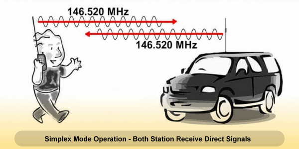
An illustration depicting a typical Sinplex mode QSO conducted between two station where 59 type signal reports may be exchanged.
If the two stations choose to use two separate frequencies for transmission and reception amongst them, then the communication mode may be either Half-Duplex or Full-duplex (Duplex). In such a scenario, one station would transmit on frequency (f1) and receive on frequency (f2). The station at the other end will reverse his TX and RX frequencies while transmitting on frequency (f2) and receiving on frequency (f1). This will result in either of the two forms of duplex communication.
So far so good… Now, what is the difference between half-duplex and full-duplex? If the two stations in QSO using separate frequencies for TX and RX, due to any reason, including limitations of their transceiver, choose to operate with a T/R switching arrangement by sequentially altering the transmit rounds between them, then the communication mode is Half-Duplex. In the case of half-duplex, the operating sequence between operators in terms of TX and RX cycles will be similar to that of a Simplex mode QSO. The only distinction is that two frequencies f1 and f2 are used by the stations as explained above.
One might ask, why would anyone want to use half-duplex when the transmission rounds are sequential and it provides a communication experience similar to simplex? There could be several reasons for doing so under special circumstances. Perhaps it could be the need to reduce the chances of eavesdropping to a certain extent, or it might be dictated by sheer necessity on account of different transmit frequency allocation to the operators in different parts of the world. In HF band, a highly sought-after station under a pileup might resort to this method that in HF radio parlance is called Split-Frequency operation… However, that’s a story for another day.
In the case of Full-Duplex operation, everything remains the same as what was described for half-duplex regarding the use of frequencies f1 and f2. The only difference is that both the stations in QSO have station equipment set up with the capability to simultaneously transmit and receive without resorting to a sequential T/R protocol. The effect is similar to the normal telephone where both stations can carry out QSO without bothering to switch rounds and thus even talk over each other. The transmitter and receiver on each side function together on frequencies f1 and f2 as described before.
Although a typical amateur transceiver including FM radio HT and base stations are capable of either simplex or half-duplex, a typical FM repeater is an example of a Full-Duplex setup. The more sophisticated Linear Transponder type communication satellites including some of the LEO amateur radio satellites allow full-duplex communication.
Does a QSO via a typical FM repeater qualify as some sort of a duplex QSO? Yes, it does… However, a QSO between two stations through a repeater is a half-duplex QSO even though the repeater operates in full-duplex mode. This limitation is on account of our station equipment that typically does not allow full-duplex but only half-duplex.
All good so far but what’s wrong with 59 reports on a repeater?
In view of what we have discussed so far, let us quickly apply the concepts to a typical repeater-based communication scenario. Since a picture is often worth a thousand words, let me present an illustration depicting how a repeater-based QSO goes through. The two stations in communication do not receive each other’s signals directly but conduct the QSO via the repeater that acts as an intermediary.
The transmission at frequency f1 from a station on one side is received by the repeater. It is demodulated. The audio is thereafter processed to clean and amplify. Thereafter, the transmit chain in the repeater modulates this audio to another frequency f2 that is offset from f1 and then transmits it. This process appears to happen simultaneously in real-time because the repeater is operating in full-duplex mode. The other station receives the re-modulated and re-transmitted content of the first station’s content on frequency f2… Similarly, when the second station transmits, it too transmits on frequency f1 that is received by the repeater to b re-transmitted on frequency f2. The first station now receives it on f2.
Note, in the case of repeater operation both stations have their transmitters tuned to the frequency f1 while their receivers are tuned to f2. This is distinctively different from the case of one-to-one direct half-duplex or duplex communication. In the direct link scenario, the receive and transmit frequencies of the two stations need to be reversed.
Having said that let us now address the core question that we have kept pending so far… Why can’t we exchange 59 type RST signal reports on a QSO conducted via a repeater?
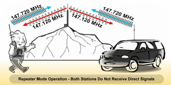
A simplified illustration to depict a typical scenario of an FM repeater based QSO where both stations copy the repeater signals and not one another.
Whatever signal-strength report that we might give out in our RST report applies to the signal of the repeater and not the other station. The other station might be close to the repeater location or quite far away. He may be running low power or high power. None of these factors matter. We will always receive consistent signal strength from a repeater. Remember, unlike linear transponders, repeaters re-modulate the audio and transmit from its fixed location at a fixed RF power.
One might say, I hear stations with different amounts of noise and loudness when I work through my local FM repeater. Some sound noiseless and clean while the others may not sound as strong and good… Very true. This indeed happens. However, this is not due to the higher or lower RF signal strength from the repeater signal at our end. It remains a more-or-less constant at our current location.
What really happens is that the signal received by the repeater from the other station before the repeater re-modulates and re-transmits might be weak or strong, or noisy or clean. In other words, the demodulated audio at the repeater’s receiver stage output might be noisy with a poor signal-to-noise ratio (SNR). The repeater is unable to clean it up. Hence, noisy baseband audio available at the output of the repeater’s receiver is re-modulated and transmitted. That is the reason for higher noise and poor audio SNR perceived while working some stations via a repeater.
The bottom line is that in the case of repeater-based operation, we do not copy the other station. Hence, the S-meter on our transceiver cannot display its RF signal strength. What the S-meter displays are the signal strength of the repeater’s signal. Therefore, when someone gives out an RST signal report during repeater QSO is actually reporting the repeater’s signal and not that of the other station.
A repeater-based communication link between two stations is a two-stage cascaded link. Therefore, there is no way for one station to receive or measure the other station’s signal strength. It is only the baseband information payload that passes through the double cascaded communication link. The only sensible and credible means of reporting one another’s communication quality must, therefore, be based on the quality of the received payload.
In the first leg of transmission from the transmitting station to the repeater, the signal quality would naturally undergo a certain degree of degradation due to various factors. This would reflect on the condition of the payload in terms of associated noise, SNR, etc. In the second leg of transmission after re-modulation and re-transmission from the repeater to the destination station, the payload quality may incrementally degrade further.
The evaluation and reporting of the overall degradation as perceived at the receiving end is perhaps the only meaningful way of reporting signal in a repeater circuit. Therefore, in the case of a typical FM repeater communication environment, it is a common and perhaps a valid practice to report only the subjective quality of the demodulated audio payload.
Due to the characteristics and the behavior of FM modulated signals, an FM repeater QSO signal reporting is generally done by stating the perceived signal Quieting Level. This is because typically FM signal quality is perceived by its inherent ability to reject the channel noise beyond a certain threshold of signal strength that is determined by SNR. Normally, one would find that a good operator would never give an RST signal report on FM repeaters. They would simply state it as Full Quieting, or Partial Quieting, etc. The reported quieting level is indicative of the robustness and health of the established communication link.


(4 votes, Rating: 5.00) - Please vote the article with your valuable star rating. Thanks! Basu (VU2NSB)


Ham Rig Reviews Coming Soon
SSN SSNf(10.7) – Real-time Solar Data


