

Low SSN Solar Cycle minima – HF bands dead?
What really happens during the low SSN conditions is that HF band propagation openings that used to happen frequently are now less frequent. The duration of these openings to a particular DX destination becomes shorter. The strength of band openings becomes shallower. However, none of these means that the bands are dead or there is no propagation. All it means is that now HF DXing requires more perseverance and greater skills. The amateur radio operator can no more take radio propagation for granted as we often do while the going is good. Unlike the usual, so-called, good propagation scenario during higher SSN conditions, now the operators need to apply their minds to leverage the whims and fancies of mother nature.
Where do we usually go wrong?
Choosing the correct band and the correct time for trying to work into a particular DX region is the key to success. For this, it is important to understand the finer points of propagation behavior that many of us take for granted and do not spend enough time trying to figure it out.
We need to understand various propagation phenomena that play up during low SSN conditions. First and foremost, since the ionospheric density is lower, the Skywave skip propagation no more happens at moderate or high takeoff angles. We need to have our antennas work efficiently at lower takeoff angles. Low angle radiations will produce a skip while higher angles will penetrate the ionosphere.
We also need to leverage phenomena like trans-equatorial propagation (TEP), etc which are prevalent. We often discount the higher frequency bands like 15-12-10m and spend more time looking for activity on the lower frequency bands… Don’t do it. We might be missing out on some of the exotic DX. Most importantly, we need to know the best region in the world to target from our respective QTH.
The other important thing about LOW SSN DXing is to pay greater attention to the antennas we use. Most of us pay more emphasis on the radio transceivers we possess. Often we tend to go for more modern and more hyped latest radio rigs. This is rarely needed. We need to focus on the capabilities of our antennas. After all, a radio station is as good or as bad as the antenna it has. The latest transceiver models can rarely do any good unless the station antenna is good.
The Mantra to success and Happy DXing during Low SSN
- Give up your stereotype operating habits and work on fresh action plans.
- If you live in the northern hemisphere then don’t waste too much time looking for East-West DX propagation openings.
- North-South (across the equator) paths will yield great success for operators living above the equator.
- Due to the sun’s sub-solar path, at this time of the season, being around -20° Latitude or lower, operators in the south are blessed with great openings provided they choose the proper band.
- Leverage the elevated ionization density of the ionosphere around the equatorial region (formed due to equatorial electrojet) and try to focus on the 15-17-12m bands.
- The 20m and 10m too may yield good results from time-to-time.
- A good antenna does not necessarily mean a higher gain antenna. The important factor is the radiation takeoff angle.
- Lower the radiation takeoff angle of your antenna, the better will be the DX communication prospects.
- Raise your antenna as high as possible above the ground with adequate clearance from metallic structures.
- A moderate gain, lightweight antenna at a greater height above the ground is far more effective than a higher gain antenna at a lower height.
- Deploying antennas at a good height above ground also need good transmission line systems.
- A transmission line with poor common mode current balance kills all possibilities of conducting low signal strength QSO because an additional 1-3 S-units of increased noise pick up will usually place a workable signal with 10-12 dB SNR below the noise threshold.
- Coaxial cable with common-mode imbalance being more-or-less vertically oriented as it runs down from the antenna behaves like a vertically polarized unwanted antenna section despite the actual antenna being horizontally polarized. As a consequence, the cable picks up unduly strong local area QRM to sink the SNR well below the noise floor rendering the antenna practically useless under Low SSN conditions. Check out the article on Noise in Radio Communication
- Under the current propagation conditions, normally, the optimum required takeoff angle is between 8-14° for the upper HF DX bands.
- Most antenna installations used by radio amateurs produce negative gains at such low takeoff angles that are often in the range of -20 to -10 dBi or worse even if the published maximum gain of the antenna for the peak of its lobe is 10-15 dBi.
- The above-cited points are the reason why we usually hear people say that the bands are dead. The fact is that the bands are not dead, it is the antenna that is actually dead.
Nevertheless, try working north-south trans-equatorial DX on 15m or perhaps even 10m. Let me assure you that you will be pleasantly surprised even if you use simple antennas like a dipole or a 3-element Yagi provided they are well designed and properly deployed. If using a dipole then ensure proper orientation of the antenna in the preferred direction.
Real low SSN HF DX opening scenarios
Without wasting more time ranting, let me present a few real HF band propagation scenarios that prevail during the low SSN phase of Nov-Dec 2019. For those who might be reading this post a few months later, there is nothing to despair about. The cited time of openings and the open bands may shift which the change in seasons as per sun’s position but band opening would still be there, perhaps at a different time. Moreover, right now as I write, we are absolutely at the rock bottom of Solar activity and hence the lowest SSN. Over the coming weeks and months, it is bound to gradually improve and the propagation scenario would become better.
In the example scenarios below, please note the following facts…
- All examples are for the 15m band, however, one could work on nearby adjacent bands with similar or better results.
- The prevailing daily SSN is zero these days but the true and effective SSN as derived from Solar Flux Index (SFI) and Ionosonde measurements is about 11 for today. For more on this, check out the article on Solar Activity and Ionosphere.
- The examples are for SSB radiotelephony with 2.5 KHz modulation bandwidth and a base noise floor limited SNR of 34 dB.
- The actual obtained SNR on SSB is in each example is better than 8-14 dB which is great for comfortable SSB QSO.
- If we were to conduct CW or PSK31 QSO, the advantage would be far greater providing us with better prospects and wider geographic coverage. We don’t need to resort to mundane and zombie QSOs through modes like FT8.
- Please note the important fact about the antenna radiation takeoff angle that I have been emphasizing all along. Every circuit path under low SSN conditions requires a low takeoff angle which may be as low as 8-10° only. Take a note of the Red-colored rectangle around the takeoff angle parameter shown in each example illustrated in the top bar.
The illustrations show projected propagation conditions on 15m band on 28th Nov’19 at UTC time specified in each example. The colors on the map represent SNR at locations around the world. Redish color depicts high SNR values while yellow, green, cyan, and blue depict progressively lower SNR. Dark green represents the approximate SNR low-end boundary of workable limits.
While assessing each of the propagation scenarios presented below, please keep in mind that propagation behavior is by-and-large reciprocal in nature. Hence, not only is propagation available from the cited locations to the DX destinations but these openings are also available from the cited destinations backward to the originating regions. In other words, there are ample propagation openings available also to the stations located at places not cited as the primary regions in the examples.
senario 1 – (South Asia to Australia, Africa on short-path)
- The propagation scenario is projected from a QTH in New Delhi, India.
- The antennas used are Dipole (@ 55ft. height) at both ends of DX circuits.
- TX power is 100W PEP, mode SSB, 1,8-2.3 kHz receiver filer engaged.
- The operating band is 15m, Operating time is 09:30 UTC.
- Effective propagation covers Australia, New Zealand, South-East Asia, West-Asia, Africa, and parts of Central Asia.
- Typical required antenna radiation takeoff angle is 9°
- Achieved SSB mode (2.5KHz Bw) SNR to Australia is 12.8 dB.
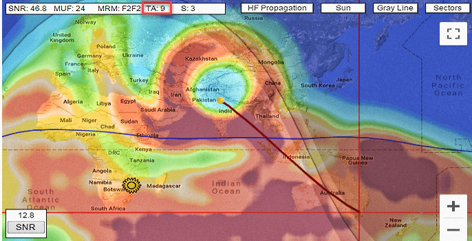
15m band opening from New Delhi, India into VK/ZL land under low SSN conditions.
Scenario 2 – (South Asia to South America, Africa on short-path)
- The propagation scenario is projected from a QTH in New Delhi, India.
- The antennas used are 3-element Yagi (@ 45ft. height) at both ends of DX circuits.
- TX power is 100W PEP, mode SSB, 1.8-2.3 kHz receiver filer engaged.
- The operating band is 15m, Operating time is 10:30 UTC.
- Effective propagation covers South America, Africa, South-East Asia, the Gulf region, and parts of South-eastern Europe.
- Typical required antenna radiation takeoff angle is 10.7°
- Achieved SSB mode (2.5KHz Bw) SNR to Brazil is 10.8 dB.
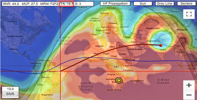
15m opening from New Delhi, India to Brazil and other parts of South America.
Scenario 3 – (Europe to Southern Hemisphere on short-path)
- The propagation scenario is projected from a QTH in Central Germany.
- The antennas used are 3-element Yagi (@ 45ft. height) at both ends of DX circuits.
- TX power is 100W PEP, mode SSB, 1.8-2.3 kHz receiver filer engaged.
- The operating band is 15m, Operating time is 20:30 UTC.
- Effective propagation covers South America, Africa, and Australia.
- Typical required antenna radiation takeoff angle is 14.5°
- Achieved SSB mode (2.5KHz Bw) SNR to Argentina is 19.4 dB.
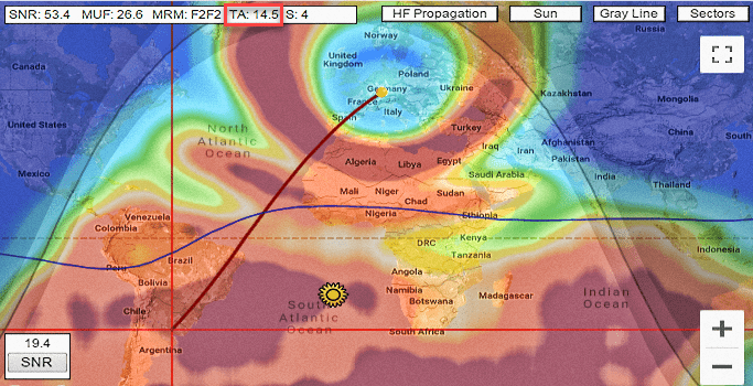
15m band opening from Germany and other parts of Europe to Africa, Australia and South America
Scenario 4 – (North America to Southern Hemisphere on short-path)
- The propagation scenario is projected from a QTH in Central central U.S.A.
- The antennas used are 3-element Yagi (@ 45ft. height) at both ends of DX circuits.
- TX power is 100W PEP, mode SSB, 1.8-2.3 kHz receiver filer engaged.
- The operating band is 15m, Operating time is 20:30 UTC.
- Effective propagation covers South America, Africa, Oceania region, including New Zealand and Australia.
- Typical required antenna radiation takeoff angle is 13°
- Achieved SSB mode (2.5KHz Bw) SNR to New Zealand is 15.4 dB.
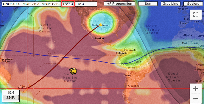
15m band opening from central part of USA to South America, Oceania, Australia, and New Zealand.
Scenario 5 – (Oceania Region to Northern Hemisphere on short-path)
- The propagation scenario is projected from a QTH in South-East Australia.
- The antennas used are 3-element Yagi (@ 45ft. height) at both ends of DX circuits.
- TX power is 100W PEP, mode SSB, 1.8-2.3 kHz receiver filer engaged.
- The operating band is 15m, Operating time is 08:30 UTC.
- Effective propagation covers Asia, africa, and entire Europe.
- Typical required antenna radiation takeoff angle is 9°
- Achieved SSB mode (2.5KHz Bw) SNR to Germany is 8.7 dB.

15m band opening from South eastern Australia to Asia, Africa, and Europe.
If all the above is true, then why doesn’t it work for me?
That is a very pertinent question. It is sadly true that most amateur radio antenna installations are often technically inadequate to deal with low SSN propagation conditions. Unlike grand propagation opening conditions where signals are S8-S9 or more and when even a coat-hanger may work as an antenna, here we are dealing with signals falling in the range of S2-S3. We cannot afford unnecessary losses, inefficiencies and spurious noise pick up spoiling our antenna performance. Any of these factors will reduce the achievable SNR and make communication impossible. This is exactly what happens in most cases.
While planning and deploying an antenna, do remember to get the best possible height, clearance from pattern distorting structures, good low loss transmission line, best possible impedance matching at antenna feed-point to get minimum feeder line SWR (using ATU in the shack to tame high feeder SWR is no good), and most importantly get rid of common-mode current flowing on the outer braid of the Coaxial cable. The Common-mode current imbalance on the feeder may be a deal-breaker…
Most radio amateurs tend to believe that if the final SWR that they achieve at the shack-end of the cable using either the internal or an external ATU is low enough, then it’s all hunky-dory… Sadly, that’s a myth. Though taming the shack-end SWR to acceptable limits is needed for the transmitter to load into the Antenna/TL system but it is not enough. SWR is only the tip of the iceberg.
Most radio amateurs tend to believe that if the final SWR that they achieve at the shack-end of the cable using either the internal or an external ATU is low enough, then it’s all hunky-dory… Sadly, that’s a myth. Though taming the shack-end SWR to acceptable limits is needed for the transmitter to load into the Antenna/TL system but it is not enough. SWR is only the tip of the iceberg.
Plan antenna installations
A majority of amateur radio operators around the world, especially those living in urban and metropolitan areas face a lot of constraints. Additional man-made noise and inadequate antennas are the usual concerns.A dipole strung up at a low height, a sloper, or an inverted-V placed in proximity to buildings, metal fittings, water pipelines, overhead wires, etc create problems. Low antenna heights and proximity to man-made objects and entities that distort radiation patterns often result in elevating the radiation takeoff angle to unacceptable limits. To compound the problem, many radio amateurs are often blissfully unaware of these catastrophic effects.
Rooftop antenna installations
People often install antennas on top of the roof of their houses using 10-20 feet long poles or mast to raise them above the roof surface. They would normally estimate the antenna height above the ground to be equal to the height of the building plus the mast length. Quite often this would work out to be 40-50 or even 100 feet. One might tend to think that this height is the height of the antenna above ground from the antenna radiation perspective.Unfortunately, the above assumption is usually quite wrong. Most modern urban buildings are built using beams and columns that contain steel. The rooftop itself is laid out using reinforced cement concrete (RCC) mix set into a TMT bar steel mesh framework. This makes the rooftop electrically conductive. Hence, the antenna sees the rooftop as the effective ground surface beneath it.
In other words, most of the time, such an antenna installation will behave like an antenna installed only about 10-20 feet above the ground. The water pipes and plumbing laid out on the roof add further to the woes. One may end up with an antenna that practically radiates most of its energy skywards and also has a fairly high takeoff angle of its major lobes.
Transmission line common-mode noise
The coaxial cable transmission line running down from the antenna into the shack may also be another big culprit. Most operators connect the coax cable directly to the antenna feed-point without bothering about the balancing mismatch that might be created. As a result, the antenna system (comprising of the antenna and the feeder) becomes prone to an extensive amount of noise pick up from the local man-made QRM sources.The transmission line begins to act as a broadband non-resonant antenna of sorts. While transmitting, it leaks a considerable amount of energy to cause EMI RFI in the neighborhood. While receiving, the effect is even worse. It picks up a lot of noise that wasn’t meant to be picked by the antenna itself. This noise adds to the signal and atmospheric noise received by the antenna increases the aggregate noise and thus reduces the net SNR at the receiver input terminals. A small amount of feeder noise pick up due to common mode current imbalance may reduce the net SNR by as much as 10-12 dB. That is a final nail in the coffin for low SSN condition DXing.
Common-mode current choking
All this is such unnecessary and avoidable waste. Either due to recklessness or ignorance, we end up killing all prospects of working DX. Some might say, oh no!… I have already taken care of the common-mode feeder current by wrapping several rounds of the coaxial cable near the antenna feed-point. So, all is good for me… Well, honestly NO! it is not. We need to attenuate the common-mode current by at least 20-30 dB for it to be effective. That would translate to about 1000-1500Ω impedance at the operating frequency. We need to do far better than winding a few turns of coax to get that impedance. Do some maths and you will find the truth.The objective of this post was to state that the bands are not really dead during low SSN, it is just that our antennas are usually no good to negotiate the conditions. I also wanted to highlight the problem areas and how they might be rectified. We need to pay a little more attention to our antennas than we otherwise take for granted. A small improvement in the antenna setup would go a long way in improving DX prospects.
73, and happy DXing… Basu (VU2NSB)


(10 votes, Rating: 5.00) - Please vote the article with your valuable star rating. Thanks! Basu (VU2NSB)


Ham Rig Reviews Coming Soon
SSN SSNf(10.7) – Real-time Solar Data


