

Does Low SWR always mean a good Antenna setup?
There are various other factors that go a long way in determining optimum antenna performance. This is notwithstanding the fact that the location of antenna installation, its surroundings, and height above ground play vital roles. Let us ignore these limiting factors because I know that most of us, the radio amateurs, are often constrained by real-estate limitations and therefore may not always be able to install our antennas the way we might have liked to.
Within the realms of the above-cited limitations, the SWR is still not the ultimate indicator of antenna system health. Let us examine why is it so, and what are the other factors that could overshadow the sense of blissful utopia that we so often tend to feel when we successfully end up with low SWR at the transceiver end of the transmission line using an Antenna Tuning Unit (ATU), etc?
What does a low SWR at the transceiver end of the feeder mean?
Typically, an antenna is connected to the transceiver using a length of a transmission line. It could be an Open-wire line, a slotted line, or a coaxial cable. Generally, one would tend to connect an SWR meter at the end of the transmission line that leads into the transceiver. If the SWR is low enough, then we tend to feel happy. Otherwise, quite often we redeem the situation by using an ATU that might be either built into the transceiver or an external unit connected to the output of the transceiver. The ATU (either manual or automatic) would transform the complex impedance that is projected by the antenna and feeder combination to a value that matches the output impedance of the transceiver. By doing this, we ensure that the load seen by the transmitter is optimum and it transfers maximum power into the transmission line system.
As a result of the above exercise, the transmitter runs happily and pushes out all the juice it can. However, is it enough? Is everything hunky-dory? Do we now have an optimum station setup?… Perhaps not!
All that we have achieved so far is a condition where the transceiver is working optimally. Does it also mean that the antenna and the transmission line setup is optimal? If not, then what else could be wrong even though the SWR is great? Let us examine several factors that could render the low SWR condition relatively less important in the larger picture.
Why might low SWR at transceiver NOT be enough to ensure good results?
Firstly, let me dispel the notion that the ATU that we typically use does anything at all to correct the SWR on the transmission line. No, it doesn’t do it. The ATU only transforms and presents an impedance to the transceiver that it would ideally like to see, without actually altering the impedance presented by the transmission line. In a way, one wouldn’t be very wrong in assuming that the ATU creates an illusion for the transceiver.
Despite the ATU, all mismatches, standing waves, current, and impedances prevailing along the antenna plus transmission line remains unaltered. As a consequence, the antenna system performance, behavior, including its shortcomings continue to remain as it is.
Before we proceed further, let us list out some of the most common myths and grossly misplaced notions related to SWR, antenna, and the transmission line… Here are some of them.
- Achieving a low SWR is the single most important factor for an antenna setup.
- An ATU at the transceiver end will reduce SWR loss on transmission line.
- High SWR on the transmission line is invariably a recipe for a poor antenna.
- High SWR on the transmission line produces excessive noise pickup and EMI/RFI.
- SWR on line decreases if Length is a specific multiple or fraction of wavelength (λ)
- Longer length of coaxial cable line will reduce SWR to improve antenna performance.
All the above statements are false and must be debunked outright. Let us dwell deeper into each of them and try to figure out the truth one by one.
Is Low SWR the most important factor for an antenna installation?
Although a low SWR on the transmission line is always welcome and effort should be made to deploy an antenna system that would inherently have as good an impedance match as practical between the antenna feed-point and the transmission line, the fact is that it may not always the matter of primary concern.The degree of emphasis on SWR boils down largely to the nature of the transmission line in use. In the case of very low loss transmission lines, high SWR is rarely an issue, whereas, for a more lossy line, high SWR might become a factor.
For instance, if the transmission line is a coaxial cable, then at the frequency of interest, especially on the higher frequency bands, it is possible that the cable might be significantly lossier. The loss per unit length of the cable at higher frequencies would be magnified by a higher SWR on the cable. Hence, while using the relatively lossier low-cost coaxial cable it is certainly advisable to attain as low an SWR as practical. This keeps the additional SWR-related cable losses minimum and consequently improves the overall efficiency of the antenna system. However, please keep in mind that neither the ATU of the transceiver nor an outboard ATU at the transceiver output will reduce the transmission line SWR. As I mentioned earlier, the ATU would only serve as an aid to present a favorable SWR to the transceiver without actually altering it on the transmission line.
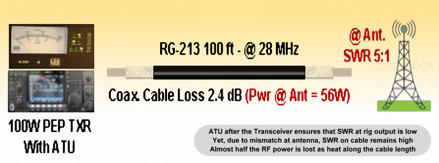
an illustration that clearly depicts the fact that even though a perfect SWR may be achieved at the transceiver output, it might not produce good results due to high SWR prevailing on the main transmission line.
On the other hand, if the transmission line is an efficient and low loss line like an Open-wire Line (OWL), as often recommended for use with several practical HF antenna systems, the line SWR is rarely of any consequence. There are so many well-established and well-known antenna configurations that work perfectly with high transmission line SWR. The G5RV, the Doublet (Double-Zepp), the W8JK, etc are prominent examples of antennas that use OWL and have quite high SWR on the line. Despite the high line SWR, these antennas perform extremely well with superb efficiency and broad bandwidth.
Will ATU at the transceiver reduce transmission line SWR?
At the risk of being repetitive, let me categorically state that it won’t. Such an ATU will only make the transceiver see the impedance that is ideal for it. This way, the ATU would primarily serve the function of creating a mirage for the transceiver, to fool it into outputting the maximum power it is designed to deliver… Nothing more and nothing less.Is High line SWR always indicative of a poor antenna?
NO, it isn’t… We have already discussed some of the reasons above. We have also seen that only in the case of lossy transmission lines of fairly long lengths, the question of reducing the line SWR becomes a factor worth considering. For, low loss lines, the possibility of reaping a similar advantage is very little.Moreover, the antenna performance is not dependent on the transmission line SWR. The antenna will continue to perform as it is meant to, irrespective of the magnitude of the line SWR. The antenna radiation efficiency is not determined by line SWR. The only thing that a lossy transmission line with high SWR might do is to dissipate (as heat) a portion of the power from the transmitter before it could reach the antenna. As a consequence, the antenna will receive less juice, as if it were connected to a lower power transmitter. The antenna radiation characteristics will not be affected or altered in any way due to the SWR.
Does High line SWR result in a more noisy antenna?
This is perhaps one of the most ridiculous arguments that I ever heard. Yet, so often I come across people who tend to believe that high transmission line SWR results in greater noise pickup, interference, and enhanced EMI/RFI. This is one of the biggest myths.The transmission line SWR has nothing to do with the noise performance of any antenna system. The noise in the form of natural noise (QRN) and the man-made noise (QRM) that might be present in the environment are typically received within the reception bandwidth by the antenna itself along with the signal. This would be the ideal case and it would represent the scenario of minimum noise that will always ride through. However, in the case of most practical antennas, there is another source of noise pickup. It is the transmission line. The quantum of additional noise pickup by the transmission line has nothing to do with the prevailing SWR but on another factor called Common-Mode Imbalance that results in the creation of Common-Mode Current (CMC). The CMC on a transmission line may be produced due to several factors but certainly not due to SWR.
I will not go into the details of transmission line noise over here because I have it fairly well covered in a separate post. Please refer to Does Coaxial Cable Choke at Antenna cut RF Noise? However, rest assured that the SWR will not contribute to making your antenna any noisier.
Does SWR decrease if line Length is a specific multiple or fraction of wavelength (λ)?
Many people will swear that this is true… However, unfortunately, it is a false notion. Right now, I won’t be surprised if several people exclaim and say… What nonsense! I have tamed the SWR and brought it under control so often by adjusting the coaxial cable length. It surely works for me! So, how can it be untrue?Obviously, so many people cannot be wrong. After all, they speak from the experience they had while setting up their antennas. let us try to find out the facts and also what caused the experience these people had. However, before we could understand more about what was going on, we need to recap on some of the basic principles of transmission line currents.
The first point to understand is that primarily, two types of RF current may flow on a transmission line. The first one is the differential-mode current that carries the desired RF signal energy from the transmitter to the antenna or vice-a-versa. The other current is the common-mode current (CMC). This one is usually the spoilsport that must be prevented and avoided under typical circumstances. The RF power transfer from the transmitter to the antenna occurs via a differential current that flows between the two conductors of the transmission line. For instance, in the case of a coaxial cable, the desired RF power flow along the inner conductor and the inner surface of the coaxial braid. The magnitude of the current is identical on both the conductors while the phase is opposite. This way the transmission line confines the power within it and prevents unwanted radiation from the transmission line. Whereas, the other (undesirable) current that might flow on the cable is the common-mode current (CMC). Though the CMC also flows through the same physical outer braid, it remains independent and electrically isolated from the differential current due to the physical phenomena of skin-effect. The CMC flows on the outer surface of the braid of the coaxial cable. Though it is a common braid, the inner surface differential current and the outer surface CMC are isolated from each other due to the limited depth of penetration of current into the thickness of the coaxial-cable braid. The isolation occurs on account of extremely small (few tens of a micron) skin-depth at RF.
It is the CMC that is responsible for the anomalous experience and all the other unruly behavior experienced by some of these operators. Not only is the CMC responsible for additional noise pickup and noise radiation by the feeder but it also results in undesirable RF current flowing back into the ham shack and the radio equipment. The CMC, depending on its magnitude might result in a malfunction of station equipment in extreme conditions, or else, in less severe cases, it will mess up with the perceived SWR on the line. It might detune the antenna in some cases while it may cause abnormal behavior in other instances. The notion of actually improving the SWR by adjusting the transmission line length is also due to the unruly effect of CMC. It just messes up with the SWR meter and measuring equipment to create a false perception.
For instance, one might notice that touching or holding the coaxial cable might change the SWR, rolling or relocating the cable might also change SWR, or cutting and adjusting cable length might also resultant in altering SWR.
CMC must be reduced to the minimum possible for reliable and repetitive results. However, many operators are either oblivious to the unsavory effects of CMC or they might simply be too lazy to take care of it. Take care of the CMC and reduce it to the bare minimum to get rid of all these strange behavior cited above. There are several ways of taming the CMC or even preventing it from being created. Use a proper combination of balance-to-imbalance transformers (Balun) wherever needed. Thereafter, if need be, do not hesitate to use a well-designed common-mode current choke on the feeder line. Refrain from using ugly baluns and opt for a good toroidal CMC choke. In some cases, it might be convenient to use transmission-line transformers using lengths of coaxial cable.
Finally, one might come across an antenna that uses your transmission line as a part of its radiating system. Plenty of such antennas is sold in the market with a lot of marketing hype. My suggestion is to avoid such antennas. They might work but they are not good enough and come with a lot of unnecessary baggage.
Will Longer length coaxial cable transmission line reduce SWR?
That’s what your SWR meter in the shack will show in many cases but don’t be fooled by it. The lower SWR on a longer coaxial cable is due to the fact that it produces more loss which swamps the SWR and makes it appear to be lower on the SWR meter. However, the SWR at the antenna end of the cable will still remain high. The lower perceived SWR on the meter is actually counterproductive. The greater loss on the longer cable will dissipate a significant amount of TX power in heating the cable than radiating from the antenna.Here are a few practical examples for practical coaxial cables as measured on the 10m HF amateur radio band.
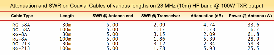
A table showing expected coaxial cable transmission line losses on account of SWR for a variety of cables at 28 MHz (10m) HF amateur radio band.
Take a look at the above table. The picture is clear. It shows exactly what happens. Take the example of RG-213. Although the mismatch at the antenna in all cases results in 5:1 SWR at the antenna feed-point, the SWR seen at the transceiver end of a 30m length cable is 3.12:1 but if we increase the length to 100m then the SWR at the transceiver reduces to 1.78:1. One might think that the antenna system is nicely setup because it shows low enough SWR even without any ATU.
However, the fact of the matter is that the situation is rather bad. Although the SWR appears to be below 2:1 with the 100m RG-213 cable, the transmission loss is rather unacceptably high. The loss is 5.93 dB which means that out of 100W pushed out by the transceiver, only 25.5W reach the antenna to be radiated, while the balance 74.5W gets lost as heat in the coaxial cable... Mind you, we took the example of RG-213 that is rather good. Consider what would happen if the cable were to RG-58A? For the same mismatched antenna, the station operator will feel so happy because his SWR meter would read 1.17:1 but he would actually be radiating only 6.7W while the rest of the 100W would be lost.
The bottom line is that although a longer coaxial cable transmission line will definitely indicate lower antenna system SWR despite a gross mismatch at the antenna, one would land up with a fairly bad antenna system efficiency.
Finally, before I wind up, let me mention that the coaxial cables are inherently lossier and hence some of the issues we discussed above apply more to them. On the other hand, open-wire lines (OWL), slotted parallel lines, etc have unit length loss that is several orders of magnitude lower than coaxial cables. Hence problems related to high SWR and long lengths are also quite less.


(4 votes, Rating: 5.00) - Please vote the article with your valuable star rating. Thanks! Basu (VU2NSB)


Ham Rig Reviews Coming Soon
SSN SSNf(10.7) – Real-time Solar Data


