Good Antenna for any Radio Station is vital
There are two basic types of antennas, the standing-wave and traveling-wave antenna. All antenna systems are developed around either of these two types. Complex structures are an extension of the basic doublet. Most antennas are resonant, however non-resonant designs are also common. Radiating elements can be oriented vertically, horizontally or obliquely depending on the design. The elements can be extended in multiples of the fractional wavelength.
Multiple elements can be placed within the near-field of the primary driven radiator to shape radiation patterns. These elements can either be parasitically driven by drawing energy from the primary radiator as in the Yagi-Uda structure or be actively driven by the source with a controlled phase relationship to produce similar effects. Antennas are very interesting and fascinating. The variety of possible designs is limited only by the ingenuity of the designer.
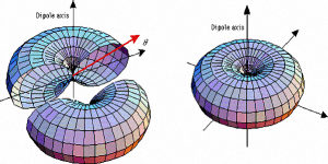 Antenna Fundamentals
For an antenna element to radiate, the RF current that flows through the element due to excitation from a transmitter initially produces a time-variant magnetic field in proportion to the magnitude of the electrical excitation. This is called the Induction field. As the current in the element reverses polarity, the magnetic field reversal also occurs. The alternating electric field and the magnetic flux, eventually detaches itself from the conductor as subsequent cycles of RF excitation are applied to the antenna wire. The Induction field energy is pushed outwards. This is when a transformation takes place which converts the Induction field to Radiation field. The Radiation field produces EM waves which is totally detached from the antenna and is self sustaining. It travels through free space at the velocity of light… Read More.
 Omnidirectional Antennas
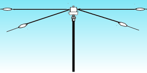
Standalone vertical antennas are usually omnidirectional unless they are placed in an array. The simplest vertical is the quarter-wave Marconi antenna. All vertically oriented antennas feature vertical polarization. Orientation of the electric field represents its polarization. The electric field (E field) is vertical and the magnetic field (B field) is horizontal. Vertical radiators may or may not require a ground-plane or a counterpoise depending on the design length and placement of feed-point. The azimuthal radiation pattern is invariably omnidirectional. This is due to geometrical symmetry around its vertical axis. They usually have low radiation takeoff angles and are good for DX. Verticals with ground-planes are less susceptible to influence of height above ground. They perform well but are not good for short distance sky-wave…. Read More.
 Horizontal Wire Antennas
Wire antennas are very popular and relatively low-cost. They are usually oriented horizontally at various heights above ground. They may also be installed as slopers or inverted-V. Standing-wave resonant wires are common but traveling-wave antennas like the Rhombic have very special features. Normal wire antennas are usually half wavelength long, however longer wires are also used. Wire antennas can be mono-banders or multi-banders. A half wave version has bidirectional broadside radiation lobes. Radiation along the wire direction is minimal unless the radiator is several wavelength long. These antennas are greatly influenced by the height above ground and also by the properties of the soil. If the soil is dry, their performance is greatly impaired. Moist soil with good conductivity and high dielectric constant improves performance… Read More.
 Yagi-Uda Antennas
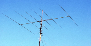
The Yagi-Uda antenna is a form of dipole array. Several dipole elements with incrementally varying resonant frequencies are placed in a coplanar configuration in parallel to the driven dipole radiator. All elements other than the driven element are parasitic elements and are placed within the mutual induction field of one another. The parasitic elements draw energy from the induction field of the adjacent element. The primary energy source is the driven element. Energy absorbed by the parasitic elements are re-radiated by them. The re-radiating parasitic elements can be viewed as independent spatially offset sources. Vector combination of several phase shifted EM waves produced by these element generate an interferometric pattern. The net effect is the directive lobe pattern… Read More.
 Cubical Quad Antennas
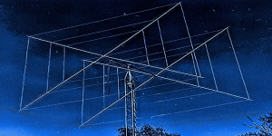
Cubical Quad is a loosely used term. Other than square or diamond shape, it can also be a triangular Delta loop. These wire loops can be single loop with bi-directional radiation pattern or have several parasitic or driven loops to form a uni-directional array. With multiple concentric loops, it is easy to fabricate a multi-band Quad. Usually they are full wavelength loops and occupy large volume but they are excellent performers. Although the gain compared to an equivalent Yagi is similar, Cubical Quads have a very important distinction that offers a perceivable leverage in HF communications. Unlike Yagi which has open-ended elements with high impedance points more susceptible to local static noise pickup, a Quad is relatively quieter making it great for weak signal DX… Read More.
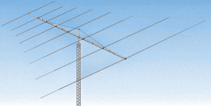 Log-Periodic Dipole Arrays (LPDA)
Log Periodic Dipole Array designs render unique broadband capabilities to the antenna system. They consist of multiple phase driven elements, progressively tapered in size in accordance to a certain mathematical paradigm. The performance bandwidth and gain of an antenna are two conflicting parameters. There is never a free lunch, hence there has to be a tradeoff between the two. The Log Periodic model has the ability to provide very wide bandwidths. It can be as high as 3 octaves or more. Hence a single LPDA can cover 80-10m (all bands) on HF. However, the tradeoff is the gain. The gain to element (or size) ratio is poor. For instance, a practical gain equivalent LPDA compared to a 3-element Yagi may need 24-25 elements. The upside is that one LPDA will cover all HF bands… Read More.
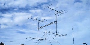 Stacked Antenna Arrays
When two or more fully functional independent antennas are place inline horizontally or vertically or a combination thereof, they form a Stacked Array (Phased Array). The distances between each antenna in a Stacked Array are determined by several design factors. The radiated energy from each of these has a predetermined phase relationship with each other. The phase difference of radiation is created by either space diversity (layout geometry) or by phase shifted power drive using phasing harness. Often both methods are used together. This results in reinforcement of radiation in the desired direction while suppressing radiations elsewhere. The end result is higher gain and a controlled lobe pattern. At times the phase shifts can be dynamically altered to create beam steering arrays… Read More.
List of Articles under this Section
Antenna Fundamentals Introduction to Antenna fundamentals In this section, we will examine some of the fundamentals of radio communication antennas. Acquiring a sound knowledge of antenna fundamentals is very important. In a radio communication environment,...Principles of Radiation How does antenna radiation occur? The basic question before us is how does an antenna work? Why does antenna radiation occur? Why does a wire carrying RF current radiates to produce EM waves which travel through free space or the...Omnidirectional Antennas Introduction to Omnidirectional Antennas In the literal sense, an Omnidirectional antenna is an antenna that radiates uniformly in all directions. However, in reality, the term Omnidirectional needs to be taken in the context...Wire Antennas HF Wire Antennas - A Primer When we speak about wire antennas, the first and foremost thought that comes to mind is the 1/2λ Dipole antenna. This is indeed a classic antenna that is not only used extensively by HF amateur...The Ubiquitous Dipole Antenna The Center-fed Half-Wave Resonant Dipole Antenna The Dipole antenna is perhaps structurally the simplest antenna to fabricate and deploy. It requires a minimal set of hardware components and is quite light-weight. All Dipole antennas...Inverted V Antenna - A popular Dipole variant The Center-fed Half-Wave Dipole Inverted V Antenna An Inverted V antenna is a very popular variant of the standard horizontal dipole. In his article, I will try to bust some of the myths associated with Inverted V and dipoles....Multiband End-fed Half-wave EFHW Antenna Multiband End-Fed Half-Wave EFHW Antenna The End Fed Half Wave antenna or the popularly known EFHW antenna has been around almost ever since the inception of HF radio. Nevertheless, the EFHW antenna had in the past, been rather...Yagi Antennas How do Yagi Antennas work? A Yagi-Uda antenna popularly known as the Yagi antenna is perhaps one of the finest inventions ever made in the field of antennas that revolutionized the world of radio communication. In the year...Cubical Quads & Delta Loops Cubical Quad antennas and Delta Loops When we think of a Cubical Quad or a Delta Loop, the picture that we usually visualize is a large multi-element structure of vertically oriented wire loops on boom and mast with a rotator that...Log Periodic Dipole Array (LPDA) Log Periodic Dipole array (LPDA) The Log Periodic Dipole Array, popularly known as the LPDA antenna, belongs to a broader family of Log-Periodic antennas. Other than the LPDA, various types of Log-Periodic antenna array structures...Stacked Antenna Arrays How do Stacked Antenna Arrays work? Stacked Antenna Arrays or Stacked Array is usually referred to as a set of directional antennas like the Yagi, the Cubical Quad, or the Helical antenna being placed in the vicinity of one another...Miscellaneous Antennas Classic miscellaneous antennas for communication Under our section on Miscellaneous Antennas, we will cover a variety of well-known antennas that do not typically fall under the genres like Yagi, Quad, LPDA, Wire Antennas, etc....


