An Introduction to Space Radio Propagation
The satellite-based communication link may be one-way like in the case of telemetry, or more often it might be a two-way link used either for command, control, or for voice, data, and other modes of information exchange. Normally, there are not many geographic entities or man-made artifacts that come in the way of the propagation path to alter the direct space wave propagation characteristics. However, most earth station based space radio communication scenarios involve using earth-orbiting satellites to form a broader communication infrastructure.
In this article, we will primarily focus on two-way communication between an earth station and an orbiting satellite. This type of communication system usually operates in the VHF, UHF, or microwave frequency spectrum. The orbiting satellites may have a variety of traits like Low Earth Orbit (LEO), Geo-stationary or Geosynchronous orbit, or could even have a highly elliptical orbit with a fairly high Apogee to Perigee ratio. Each of these orbital modes throws up some unique challenges. The LEO satellites are usually placed in polar orbits with varying degrees of orbital inclinations that determine their global coverage footprint in terms of the range of latitude they cover.
An LEO satellite may be placed in an orbit with a high angle of inclination (angle between the equator and the satellite path as it crosses over the equator), it is then generically known as the Polar orbit. However, if the angle of inclination is shallow, then it is called a low-inclination near-equatorial orbit. A special variant of LEO polar satellites is the Sun-synchronous polar satellite. We dwell into these satellite orbital variants in detail in our dedicated article on Earth Satellite Orbits.
There is another form of space radio communication that is of special interest to radio amateurs. This is the art of using the moon as a large reflector to bounce signals off its surface to establish communication between two amateur radio stations located across great distances on the globe. This is called Moonbounce or Earth-Moon-Earth (EME) communication. This communication mode is very challenging and it involves several other finer nuances of space radio propagation that may not be applicable to satellite-based radio systems.
Factors affecting Space Radio Propagation
Although, as I mentioned earlier, the primary propagation mode involved in space radio communication is the direct space wave but earth-based space radio communication is not always as simple as that. The path link between the earth station and outer space is invariably a trans-ionospheric path which means that the propagating radio signal has to always penetrate through the ionospheric layers. The ionosphere alters the propagating radio wave characteristics in several ways and with magnitudes depending on the frequency used.
Some of these effects that modify the propagation are…
- The alteration in signal polarization by Faraday Rotation.
- Doppler Shift of both downlink and uplink frequencies.
- Ionospheric delays (phase shift and group delay).
- Refraction, absorption, and ionospheric scintillation.
- Time dispersion effects, etc.
In the higher frequency microwave region (typically beyond 1 GHz), some additional effects of the atmosphere (Troposphere) may also play a role to cause signal scattering, tropospheric scintillation, as well as frequency-dependent signal absorption.
The other important factor to keep in mind is the perpetual movement of the satellite in orbit that causes a continuous change in distance between the earth station and the satellite with ever-changing relative velocity. The net effect of this phenomenon is to produce a Doppler Shift. This is a basic physical phenomenon that alters the frequency of the signal that arrives at the receiving end. The magnitude of the doppler shift is maximum when the satellite is at a low elevation near the horizon while it gradually reduces to zero at the satellite zenith when it is closest to the earth station. Let us now examine these effects.
Effects of the Ionosphere on Trans-Ionospheric Radio signals.
I will now briefly touch upon some of the prominent ionospheric effects that affect trans-ionospheric space radio propagation. Later down in this article, we will examine a few of them that make a considerable difference. All these effects are frequency-dependent and their effects become less in magnitude with the increase in frequency. VHF is more susceptible to these phenomena while UHF and microwave frequencies as progressively more immune.
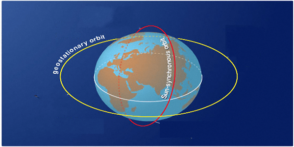
A typical Polar (Sun-synchronous) orbit vis-a-vis a Geostationary orbit around Earth.
The phenomenon of scintillation may occur both in the lower atmosphere and the ionosphere. At VHF/UHF, the ionospheric scintillation is more prominent, whereas the tropospheric scintillation is more pronounced as we progressively use higher frequencies in the microwave region. Irrespective of where it occurs, scintillation is largely responsible for the rapid variation of signal strength in the form of fast fading that resembles flutter. Scintillation is attributed to the turbulent refractive index inhomogeneity in the propagation medium. Ionospheric scintillation occurs because of the irregularities in electron density in the ionosphere, whereas, tropospheric scintillation is caused by irregularities in radio refractivity as the wave travels through different air densities in the troposphere.
A slow fading effect may be contributed by variable scattering and absorption of the signal by either or both the troposphere or the Ionosphere. In the case of the Ionosphere, these effects are attributed to the slow drift of plasma clouds and their non-homogenous ionization density. The Tropospheric effects are usually dominant in the microwave region and are caused by the absorption and scattering of the signal energy by the particles, particularly water droplets, in the propagation path between the satellite and the earth station.
Rain droplets absorb and scatter the signal energy and cause its power level to attenuate to a value depending on the signal frequency, as well as the size, amount, and shape of the droplets that the propagating signal passes through and also the intensity of rain. Many of you might have noticed that the DTH satellite television reception often becomes intermittent when there is stormy weather with heavy rainfall in the neighborhood.
Another phenomenon that needs mention is the deviation of the signal as it propagates through the ionosphere. This occurs due to the stratified nature of the ionosphere and the progressive variation of plasma ion density through the ionospheric layer slabs. The net effect is that quite often VHF and often UHF signals appear to arrive at a slightly different elevation angle than the physical elevation angle of the satellite. This effect is more prominent when a satellite is at a low elevation above the horizon.
Faraday Rotation – A major role in Amateur Satellite communication.

An animation illustrating how the polarization of a propagating wave changes as it passes through a plasma layer (shown as rectangle box) in the presence of magnetic field.
In the adjacent animation, one can visualize what happens. As the propagating radio wave passes through a slab of ionized plasma in the ionosphere, it is acted upon by the geomagnetic field. This causes the polarization of the propagation wave to shift by a finite magnitude of angular rotation around its propagation axis.
The denser the ionosphere during moderate or high SSN conditions, the greater is the polarization rotation. Daytime ionosphere causes larger magnitudes of rotation in comparison to the night due to higher prevailing ionization densities. The lower the frequency, the greater is the magnitude of angular rotation. VHF suffers the most followed progressively lesser for UHF and Microwave. Solar-Magnetic storms that disturb the geomagnetic fields modulate the rotation angle and my often result is a fast and random change in angular rotation of the wave polarization. The magnitude of rotation also varies with the angle at which the signal penetrates the ionosphere. Hence, it continuously varies as an LEO satellite hurls across the sky.
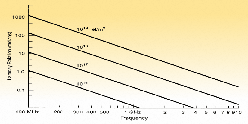
A chart depicting the expected magnitude of angular rotation on account of Faraday effect at various frequencies during different ionospheric plasma densities.
The basic concept behind cross-polarized antenna attenuation is that for two antennas to function efficiently over a direct wave LOS communication link, it is vital to ensure that the antennas at both ends have the same polarization. This is the most efficient scenario. If we were to gradually rotate the antenna at one end on its boom axis to progressively change its polarization then we notice that the signal strength at the receiver starts falling. Initially, with a small polarization mismatch, the signal loss is small which grows rapidly till it becomes impossible to receive any signal when the polarization mismatch between the two antennas becomes 90°. In other words, if the signal arriving at the receiver antenna has a polarization orientation other than that of the antenna, the signal strength at the receiver falls till it theoretically becomes zero when the mismatch becomes 90° (Orthogonal polarization).
The effect of Faraday rotation can hence cause deep fadeouts and even blackouts during QSO while using a linear polarized antenna for satellite communication. However, there is always a silver lining to any situation that might appear to be gloomy at first. So is it in this case… The loss due to polarization mismatch grows very slowly in the event of a small angular mismatch. Even when the mismatch is as high as 45°, the loss is only -3 dB, while a 60° disorientation will cause -6 dB loss. However, beyond this point, further polarization mismatch loss starts increasing rapidly till we reach an infinite loss condition at 90°.
This is known as the Polarization Loss Factor (PLF) and is determined by a very simple equation given below…
PLF = Cos2(θ)
— OR —
PLF(dB) = 10 x Log(PLF)
Where θ is the polarization mismatch angle.
The important takeaway from the above discussion is that radio amateurs often choose to live with Faraday Rotation and its detrimental effects simply by tolerating it. They often tolerate short spells of deep fadeouts, or else, they often use a hand-held Yagi antenna and point it to the passing satellite while also twisting it around on its axis to maximize signal strength. This is generally feasible because most amateur satellites are in fairly low orbits at a short distance and hence their signal power density at the earth end is fairly strong. Moreover, the hand-held Yagi antenna has a fairly wide radiation beam which makes it rather easy to point it towards a moving satellite.
Having said that, let us turn our attention for a moment to the more serious and ambitious radio amateurs who pursue satellite communication. They usually have good antenna setups which are often steerable antenna stacks on dual-axis Azimuth-Elevation (Az-El) rotators that can automatically track a satellite pass based on predetermined sub-satellite paths. They also often use cross-polarized or circular polarized antennas like the crossed-Yagi or axial mode helical antennas to address several signal polarization-related issues. More on this in our our article on Satellite Communication under the Space Radio section of our website.
Doppler Effect on Space Radio Communication
We might all have encountered Doppler Effect many a time in our day-to-day life, yet perhaps may not have attributed it the specific physical phenomenon. The horn or whistle of a passing vehicle or train would sound shrill as it approaches us but suddenly it sounds less shrill as it passes by and moves away from us. Although the pitch (frequency) of the sound of the horn is fixed, our ears perceive the variation of pitch. This is on account of the Doppler effect which actually alters the frequency (wavelength) of the sound falling on our ears due to the relative motion between us and the moving train.
It is the same effect that plays out with radiofrequency waves associated with satellite communication. Due to the orbiting satellite that moves across the sky from one end of the horizon to another from our perspective on earth, there is a continuous change in distance between the passing satellite and us. The velocity of the orbiting satellite is quite high resulting in relative velocity between it and us, the observer on earth. Moreover, due to the nature of the satellite orbital path, the relative velocity between us is not constant but changes continuously.
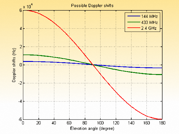
Typical magnitude of Doppler Shift of propagating radio wave at various frequencies for overhead satellite passes. The Doppler shift is low at 144 MHz and it increases with the frequency band.
After this point, continuing further along its orbit, the satellite begins to move away from us and the relative velocity begins to build up again. This time, since the satellite is moving away from us the signal wavelength appears to expand resulting in a negative Doppler frequency shift. The frequency of the signal received by our earth station is now less than the link frequency. As the satellite moves further away to eventually dip below the horizon on the other side of its pass, the amount of Doppler shift continuously keeps increasing making the received frequency gradually become lesser.
The problem created by the Doppler shift in the LEO satellite communication scenario is that we can no longer transmit on the satellite’s receiver frequency. Similarly, the signal transmitted by the satellite can no longer be received by tuning our station receiver to the designated frequency. To make matters worse, the frequency shift for both transmit and receive is not fixed. They continuously vary with time during the progression of the satellite pass.
The satellite doesn’t make any corrections at its end. It couldn’t care less… Hence, the onus of correctly counter-shifting our transmitter frequency and receiver tuning continuously to offset the Doppler shift effect lies with us on earth. If we make mistakes or do not make continuous, real-time corrections on our transceiver, then technically, communication might not be possible. The other important factor is that the magnitude of the Doppler shift is proportionately higher at a higher frequency. Hence, a 2m (VHF) satellite link will suffer a lesser shift, while a 70cm (UHF) mode will have approximately 3x greater magnitude of Doppler shift and so on.
In amateur radio satellite service, modulation modes like SSB are most sensitive to Doppler. The reason is that even around a hundred Hertz frequency-shift may make the speech sound quite horrendous and at times unintelligible. Therefore, those of us who use satellite linear transponders to conduct SSB and related mode QSO via LEO satellites have to address the real-time Doppler shift pretty accurately. We do this using various means, both manual as well as automatic. However, expanding on these would be beyond the scope of this article and hence, I am adding dedicated articles under the Space Radio section to address them.
Fortunately, the situation is not so gloomy as it might appear. We amateurs are quite resourceful and found ways of largely circumventing the difficulties posed by the Doppler shift. To bring amateur satellite radio with the reach of operators with average skills and knowledge, we have chosen to deploy and popularize other modes of modulation that are less sensitive to Dopper shift and also have the ability to capture and lock on to the transmission properly even though the receiver may not be exactly tuned to the transmit frequency. The aptest radio-telephony modulation mode to serve the purpose is Frequency Modulation (FM).
FM LEO satellites are used by abundant radio amateurs around the world using their regular 2m/70cm base station as well as hand-held transceivers (HT). The FM LEO satellite’s orbit is pretty close to the earth. Hence, the longest satellite distance near the horizon is usually less than 2000 Km while the nearest pass point may be as close as 350-400 Km only. This allows operators to use FM and run low power. Quite often effective QSO is possible with FM power output as low as 2-5 Watts. Most of the smaller amateur satellites too run TX power of 1-5 Watts. Although, with simple hand-held Yagi antennas, it may not be possible to acquire a satellite near the horizon, however, 30° or higher elevation angles it is generally a cakewalk. Moreover, the added advantage of working via LEO satellites at higher elevation angles is that the effect of the Doppler shift is far less pronounced thus making life easier for the average amateur radio operator.
Beam Deflection due to Ionospheric Refraction
The presence of the intervening ionosphere in the trans-ionospheric earth station to satellite path can produce a certain amount of signal path deviation due to refractive beam deflection while it is passing through the ionosphere. Normally, the effect is insignificant at high microwave frequencies, however, at VHF it may manifest as a noticeable phenomenon that VHF satellite link operators need to be aware of. The amount of beam deflection is more prominent during high SSN conditions, especially during the top of a solar cycle. This may occur more often during the day but this effect is seldom an issue during the night.
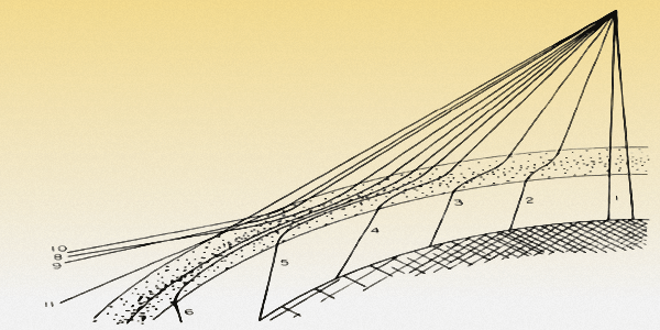
A graphic representation of the deflection of satellite signals to appear at the ground station from different elevation angles on account of ionospheric refraction.
Let us examine what really happens… When a satellite is visible at a low elevation angle near the horizon, the angle of incidence of the signal arriving from the satellite is very shallow as it strikes the ionospheric layers from the top. When the SSN is high, the ionospheric slab density is also high. This results in high ionization density with elevated Total Electron Count (TEC). The ionospheric layer slabs are thicker with a strong plasma density gradient. In such a case the effective MUF of the ionosphere for low grazing angle signal incidence will be high enough to deflect the signal significantly as it propagates through the ionospheric slab. Rather than traveling in a straight line, the VHF radio waves might travel almost horizontally through the ionosphere for a considerable distance before it emerges from the bottom of the ionosphere to travel further towards earth in a straight line.
For the earth station, the signal now appears to arrive at an angle that is higher than the actual elevation angle of the satellite. During moderate SSN daytime satellite passes, this elevation angle error may be as high as 15-20° or even more when the satellite is near the horizon. Apart from the beam bending effect of the ionosphere, even the troposphere often adds further to the effect on account of super-refraction.
In the above situation, if the earth station were to point a narrow beam antenna towards the expected elevation angle of the satellite, it would be way off the mark. The actual angle at which the signal arrives is higher than what is expected. A reorientation of the antenna elevation might be required to maximize the received signal. The worst part is that there is no way to predetermine the angle of arrival of the signal. The situation is fluid and unpredictable that will vary with the continually altering dynamics of the ionosphere. Moreover, the ionospheric dynamic changes may be rapid enough to cause deep fast fadeouts and flutter.
However, the above effect may not bother an average amateur radio satellite earth station operator. Firstly, most amateur radio operators use beam antennas that have a fairly broad elevation lobe that covers a wide elevation angle at any time. Secondly, due to the nature of most amateur antenna installations, they would anyway rarely be able to acquire a satellite at low elevation angles near the horizon. Sufficient clearance from ground-level obstructions like buildings, other man-made structures, or natural topological entities like hills, etc is usually not possible for a typical amateur radio satellite station antenna. Most operators are content with working through satellites when they appear at reasonably higher elevations. At these higher elevations, since the angle of incidence of satellite signals is no more shallow enough, the ionospheric beam deflection begins to become insignificant.
Miscellaneous effects detrimantal to space radio propagation.
Other than some of the prominent phenomena that significantly affect propagation, there are several other phenomena that too play a role in molding the typical outcome. However, since they do not produce a marked effect especially on the typical modulation modes used by radio amateurs, I will not dwell deeper into them in this article. However, I will cover most of them in separate articles on this website organized under relevant sections. These relatively lesser discussed effects include scattering, absorption, scintillation, diffraction, etc.
Work satellites with a few watts? Really! Are you kidding me?
This is a question that I have been asked a million times by various radio amateurs. With my 5-8W 2m HT I can usually reach only a few kilometers, so how is it possible to reach a satellite that is 500-1200 Km away with as much or lesser power?
Yeah! Sounds crazy? No? Hmmm… Maybe not. Everything has solid scientific logic. Some people might be surprised that we often need perhaps far less than 5W TX power (maybe less than 1W) to establish reliable communication across several thousand kilometers in space. Various inter-planetary space probes have been regularly sending us telemetry data from outer space with 1W or less TX power.
The impediments to radio wave propagation in free space are minimal as against what happens in the case of terrestrial radio communication. The terrestrial communication link suffers from various detrimental effects that I have covered in the articles on VHF/UHF, & Free Space Communication and the article on Ground Wave Propagation. Please refer to these articles for a recap.
The only major cause of signal strength reduction with distance in free space is on account of the energy density spread out over larger distances. I will give a simple example of the magnitude of signal strength reduction on account of this to provide a perspective. However, there are other phenomena that too marginally add to path attenuations.
L(dB) = 20 x Log(D) + 20 x Log(f) + 32.4 – GT – GR
Substituting the values…
L(dB) = 20 x Log(1000) + 20 x Log(144) + 32.4 – 3 -3
— OR —
129.56 = 60 + 43.16 + 32.4 – 3 – 3
Hence, the net path loss across 1000 Km on 144 MHz circuit is 129.56 dB.
If the TX power is 5W as we assumed earlier, this translates into 6.99 dBW (36.99 dBm). Let us calculate the signal power into the RX antenna…
-122.26 = 6.99 – 129.56
The signal power induced into the receiver antenna at the far end is -122.26 dBW.
Translating the above power to the receiver antenna induced voltage gives us…
-122.26 dBW = 5.94-13W = 5.45-6V (@ Z=50Ω) = 5.45μV
Hence the receiver antenna is induced with 5.45μV signal which is adequate for most communication modes used for amateur radio satellite operation. Even if the TX power had been 1W instead of 5W, the induced RX antenna voltage at 1000 Km distance would have been about √(1/5) lower. Hence, with 1 W TX power the RX antenna voltage will be 2.43μV… This too is adequate for a comfortable QSO.
Remember that there is no such luck when it comes to terrestrial VHF radio communication. Many other factors play their role to attenuate the propagating signal down to much lower levels.


(17 votes, Rating: 5.00) - Please vote the article with your valuable star rating. Thanks! Basu (VU2NSB)


SSN SSNf(10.7) – Real-time Solar Data