Ionospheric Skywave Propagation – A Curtain Raiser
These are the positions at which we have significantly more dense ionization compared to the intervening space. Due to high charge concentration, these ionospheric layers interact with the propagating EM wave and produce unique phenomena resulting in the bending of EM radio waves. For the purpose of simplification, we will, for the time being, ignore the presence of lower density ionization in the inter-layer intervening space and presume each ionospheric layer as distinct ionized entities.
Each ionosphere layers (D, E, F1, and F2) have a few common behavioral traits which we will examine first before looking into their distinct properties. The first thing that we must focus on is the fact that each ionospheric layer forms a canopy around the earth at its own specific height, in the form of a concentric sphere. The thickness of each layer is several kilometers wide in altitude.
The second thing to remember is that the ionization charge density within a layer is not constant or uniform throughout its thickness. The charge density distribution through the layer thickness varies in a gradient, with the highest ionization density lying somewhere in the middle of the layer thickness. Hence each ionosphere layer is considered as stratified with non-homogenous ionization density.
The genesis of the Ionospheric Skywave

Common propagation modes for HF radio communication.
An RX station at the return location can receive the signal. On completing the first hop the radio wave that hits the earth surface at an angle can reflect back from the surface and begin the second leg of its skyward journey. The second hop, which reaches the ionosphere at a further distance is bent back (refracted) by the ionosphere to be returned back to earth. Multiple hops or skips can continue in cascade, providing the ability to the radio wave to travel around the earth if the conditions are suitable. Therefore the radio wave can bounce to and fro between the spherical earth surface and the ionospheric layer canopy that exists around the earth. The space between the earth and the ionosphere form a good spherical duct allowing HF radio waves to travel around the world by bouncing away.
Let us now examine if the ionosphere would always return any radio wave back to earth, or is it selective in its behavior? Will the ionosphere bounce back radio waves of any frequency, or is it choosy? Will it bounce back a radio wave irrespective of the angle at which the wave strikes it, or is it finicky? All these questions are vital and determine the way the ionosphere treats the radio wave.
The treatment meted out to a radio wave by the ionosphere is determined primarily by three factors. These factors are the Frequency, Angle of Incidence, and Ionization Charge Density. We will now examine each one of them independently while keeping the other two as constant for simplicity. In the following discussion, we will often loosely use the word reflection, whereas the scientifically correct term for the process of ionospheric bending (deflection) of the radio waves is refraction.
Frequency Dependency of the Skywave
The ionospheric behavior is indeed frequency-dependent. In other words, the ionosphere layer will efficiently reflect some radio frequencies, while it may absorb some frequencies and allow some others to penetrate through it. Let us assume we have a situation where the ionosphere layer has a fixed charge density and a TX station sends out a radio wave at any fixed angle towards the ionosphere. Keeping the above two factors constant, if we now vary the frequency of the transmitter and vary it gradually from the low end of the HF frequency spectrum to the high end by changing from one band to another, we will find a distinctively different ionospheric reflection behavior.
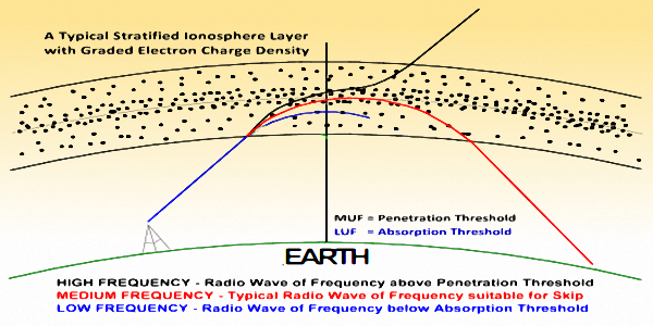
Frequency dependence of Skywave propagation at a fixed angle of incidence.
Progressively as we continue to increase the frequency, the RX received signal rapidly becomes stronger. The RX signal strength stabilizes at a point and further frequency increase does not increase RX signal strength. This indicates that the ionosphere is now efficiently reflecting back all signal energy without any significant absorption. This broadband of frequencies where the RX signal is strong is the range that can be used for effective communication using this ionospheric layer.
If we continue to increase our TX frequency further, we will discover a sudden threshold point above which the RX station abruptly stops receiving any signal. This frequency is called the Penetration Frequency Threshold. What really happens is that the radio wave at that frequency fails to bend enough to return back to earth. In fact, it penetrates through the ionosphere layer to travel higher and beyond towards outer space. Any further increase in TX frequency beyond this threshold will only make the penetration smoother and more efficient, but the signal will never return back to earth. This is why VHF and higher frequencies are used for space communication, due to their ability to penetrate through all the layers of the ionosphere.
To recap what we observed, we find that the manner in which the Ionosphere treats the radio wave is frequency-dependent. The radio waves with frequencies below the Absorption Frequency Threshold will be completely absorbed by the ionosphere and will never return back. These radio waves dissipate all their energy in the ionosphere in the form of heat. The radio waves with frequencies above the Absorption Threshold and below the Penetration threshold will reflect back to earth and is usable for HF communication. All frequencies above the Penetration Threshold will escape into outer space.
The angle of Incidence of Skywave
Let us now examine a situation where the frequency of the radio wave and the ionospheric charge density are both held constant. Let the variable factor be the angle of incidence (beam angle) at which the radio wave leaves the transmitting antenna and hits the ionosphere.
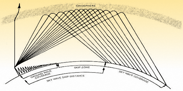
Skywave skip propagation via an ionospheric layer at different angles of incidence.
As we further reduce the radiation angle, the skywave reflection continues to occur, while the distance covered by the hop (skip) increases proportionately. You can visualize it by means of simple geometry. As the angle at the corner of the base of a triangle is reduced, the length of the line at the base of the triangle starts to become longer. Hence, the lower the angle of radiation from the antenna, the longer will be the distance of hop measured along the earth’s surface.
If we continue reducing the angle of radiation further, we will perhaps come to an angle when once again the ionospheric reflection fails. We discover that we do not have a skywave reflection anymore. At such very low angles, the radio wave does not return back from the ionosphere. This shallow angle is the Absorption Angle Threshold. At radiation angles below this threshold, skywave reflections do not occur.
There is another noteworthy aspect of the Penetration Angle Threshold and the Absorption Angle Threshold. These angles are not constant values. They vary with the frequency band of operation as well as the charge density of the ionospheric layer. However, due to frequency change or ionosphere density change, whenever one threshold values increase or decrease the other threshold value also changes proportionately.
What we have seen so far leads to some very interesting scenarios in the world of HF Skywave propagation. Some HF frequency bands work better for short-distance work, whereas other bands are more suitable for long-distance work. The behavior is further influenced by the photo-ionization charge density of the ionosphere. Daytime or nighttime influence the ionospheric densities and hence also influence skywave propagation. We will summarize this after we take a brief look at the ionospheric charge density dependency below.
Ionosphere Charge Density Dependency of Skywave
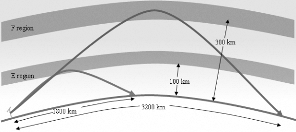
Ionospheric hops from different layers based on frequency and layer charge density.
You may recall that ionospheric layers are formed due to the effect of solar radiation. The density of these layers or their very existence is dependent on the diurnal (day or night) cycle. Of course, the charge densities also vary in accordance with the seasons, solar cycles, and several other factors. The bottom line is that the ionosphere charge densities vary considerably all the time. Normally the charge density will be very low during the winter night especially when the SSN is low. This density will be highest during the summer afternoon while the SSN is high.
Let us now examine the general effect of this density variation on skywaves. Let us see what happens when the radio wave at a fixed frequency hits the ionosphere at a fixed radiation angle. If the ionospheric layer charge density is very low, then the radio wave will perhaps penetrate the layer with very low losses and continue traveling outwards into the sky. If we now have a situation where the charge density of the layer increases gradually, we discover that above a certain density, the skywave reflection begins. This is the Penetration Density Threshold. Skywave propagation continues to work as we gradually keep increasing density. However, we reach an Absorption Density Threshold beyond which higher density will prevent sky-wave reflection and all radio energy will be absorbed by the ionosphere layer.
The conclusion we can draw is that at lower ionosphere charge density, the possibility of using lower frequencies for effective communication becomes better, whereas when the charge density is high then a higher frequency band result in better HF communication.
General Skywave Characteristics
Barring the points on the surface of the earth, either land or water, where bouncing back of radio waves occur due to reflection or scattering, the entire gamut of propagation effects related to Ionospheric Skywave bounceback is related primarily to a single physical phenomenon of refraction. HF Skywave propagation, in all its glory, occurs due to a change in the refractive index of the ionospheric medium encountered by radio waves in their path. The refractive index gradient of the medium that varies at different locations in the ionospheric region gives rise to Skywave propagation.
If the refractive index of the entire atmosphere had been uniform and homogeneous, then there would have been no Skywave propagation. The atmosphere is complex in composition. Moreover, thanks to the sun that continues to spew sub-atomic particles towards earth along with colossal magnitudes of high photon energy X-Ray radiations, we have this phenomenon of HF Skywave radio propagation on earth, that we so often take for granted.
Normally, the refractive index gradient that facilitates Skywaves lies in a region of the upper atmosphere that we call the ionosphere. Various layers of the ionosphere are many kilometers thick in height and also feature an ionization density gradient. At the bottom and the top edges of any ionospheric layer, the ionization density is minimum, whereas, it is highest somewhere in the mid-region of its slab thickness. Although the gradient of Ionospheric layer density is almost invariably in the vertical direction, there are situations when an ionospheric layer may display moderate horizontal gradient characteristics too. This often happens in the direction of a change of latitude.
As we move horizontally within an ionospheric layer towards the equator, it is not so uncommon to find a slow increase in ionization density. The net effect of the horizontal gradient is to divert the propagating radio wave slightly away from the geometric great-circle path. When this happens, we call it Skewed-path propagation, a phenomenon that could occur many a time on low and mid-frequency HF bands.
One might have thought that since the ionization density of ionospheric layers has high inertia to change, they might allow stable communication with constant signal strengths. Well, that does not normally happen. The ionospheric layers are like large drifting clouds of plasma that form concentric canopies around the earth. These cloud layers drift along in both latitude and longitude. This makes their refractive index density as well as the gradient to vary with time.
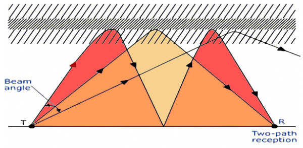
Multi-path mode Skywave propagation where signal reaches destination along several paths.
Skywave skip propagating signals encounter path losses like any other form of radio propagation. However, several factors make the propagation path loss behavior far more interesting and intriguing than other typical modes of propagation. One might intuitively tend to conclude that the longer the distance of the DX station, the greater will be the net propagation path loss. Is it how it happens even for ionospheric sky-wave propagation?… I am afraid, NO… There is no such simple pattern. Very often long-distance (DX) stations might be far stronger than relatively nearby stations. This is something that is unique to this mode of HF propagation.
The propagation opening to a DX location will depend on whether the signal path falls in the daylight or nighttime zone. It will also depend on the ionization density of the ionospheric layers that lie along the path. It will depend on the prevailing MUF (Maximum Usable Frequency) of the ionosphere at the ionospheric refraction points. The correct selection of the operating frequency band will either make or break an HF Sky-wave communication. BTW, the MUF too is not an absolute constant. The MUF varies with the angle of incidence of the Skywave on the ionosphere. We often find the specified MUF qualified with a number (e.g. MUF(3000)) designating the skip distance where the skip distance for any ionosphere layer is related to the angle of incidence of the Skywave. We will elaborate on this in a separate article.
The situation is rather fluid, and the frequency band selection for viable contacts will change from hour to hour or even less. It will also depend on the total number of skips needed to cover the distance. Based on the ionization densities, it will also largely depend on the antenna characteristics, especially the optimum radiation take-off angle of the antennas at both ends. There are many such variables that could determine the ultimate outcome.
I will explain the effects of all these factors and many more in a subsequent article under this section. I will also explain how to make an informed decision on the selection of operating parameters. However, for the moment, one should know that quite often long-range contacts may be possible while short or moderate distance ones may fail or vice-a-versa.
Daytime Ionosphere influence on Skywave
During the daytime, on the daylight side of the earth, there are four distinctive ionospheric layers. The D, E, F1, and F2 layers form the ionospheric canopy. Typically, the D-layer produces unacceptably high signal attenuation on the low-frequency HF bands rendering them practically useless. The most important layer that is instrumental in effective radio communication is the highest layer, the F2 layer. However, under the conditions of moderate to high SSN, the E-layer and the F1 layer often play a role.
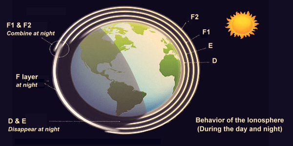
Illustration of Ionosphere layers during daytime and at night.
Many physical phenomena play a role to mold the ionospheric propagation behavior both during the day as well as night. However, there is one phenomenon that stands out and provides exciting HF radio communication possibilities. This opportunity occurs twice a day, once during the local sunrise and the other during local sunset. Radio amateurs term these prospects as Grayline propagation conditions. As the earth spins on its axis creating day and night transitions, the dawn and the evening twilight time is when a great circle path along the day-night terminator (transition) line is produced on the surface of the earth due to the illumination from the sun.
For two DX stations lying on this day-night terminator line at simultaneously at two distant geographic locations, the prospects of short duration propagation opening develop between the two stations. This Grayline propagation opening lasts for about 10-20 minutes only. As each of the radio stations experiences morning or evening twilight, then the propagation opening may on some preferred band open up by building up signal strengths rapidly. This condition may hold for a few minutes before the signals start becoming progressively weaker as the band opening eventually closes down.
Experienced amateur radio HF operators leverage the Grayline propagation as well as many other exciting HF radio ionospheric phenomena regularly to establish DX contacts around the world. As I mentioned earlier, we will dig deeper into each of these phenomena in subsequent articles.
Nighttime Ionosphere influence on Skywave
At night, the ionospheric HF propagation scenario alters drastically. As a region on earth spins into darkness after nightfall, the ionospheric canopy above that area no more receives any solar radiation to help sustain the ionization. Electron recombination begins and very soon after sunset, the density of free electrons reduces considerably. This alters the refractive index of the ionosphere and thus alters the way it would let HF Skywave propagation happen.
Earlier during the day, due to higher density ionization, higher frequency signals could propagate, whereas, during the night, due to lesser ionosphere density, the daytime frequencies are too high to be refracted back towards earth. They penetrate the ionosphere to be lost into outer space. Now, effective activity shifts to lower frequencies. The lower frequency bands that were not workable during the day due to various reasons including the adverse absorption effect of the D-layer, now, spring back to life.
After sunset, the D-layer would very quickly disappear due to the absence of solar illumination and so would the E-layer which becomes very thin and almost non-existent. We are now left only with the F layers which too would combine into one. The daytime F1 and F2 layers combine at night to form a single layer. The combined layer is called the nighttime F2 layer which happens to be at a higher altitude than its daytime manifestation. This provides a bonus effect. The increased height of the F2 layer at night allows larger distance coverage with each skip.
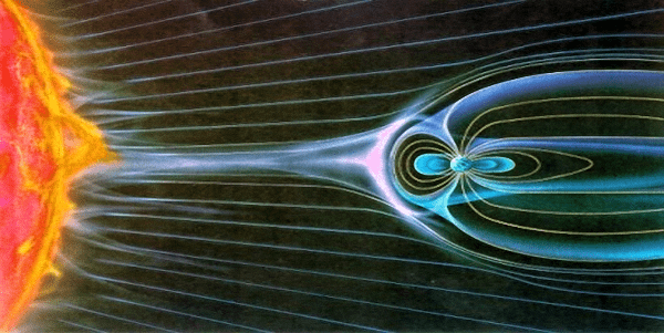
Nighttime ionosphere F-layer may get elevated beyond normal altitude due to extended Magnetotail during strong solar winds.
One might ask, why does this huge elevation of the F layer occur? Since a proper explanation would require a fairly lengthy and descriptive narrative supported by illustrations, I will defer the topic to a separate article. However, briefly speaking, it is caused by the solar winds, which after encountering the earth in its path, flow around the earth leaving a long tail on the far side.
The higher the solar wind velocity, the more pronounced is the tail and its associated forces. It is similar to the wake of a ship sailing through the waters. The solar wind tail created on the far side of the earth disturbs the earth’s magnetic field (Magnetosphere) and drags the field lines further away from the earth creating what is called the Magnetotail. As a consequence, the ionosphere comprising of charged electron cloud also gets pulled along with the magnetic field lines. Hence, we get an elevated ionosphere.
Let us leave our discussion at that and conclude this article. However, I am committed to present in-depth explanations of everything we discussed so far and much more. I will follow up with various articles on these topics under this section.


(33 votes, Rating: 5.00) - Please vote the article with your valuable star rating. Thanks! Basu (VU2NSB)


Ham Rig Reviews Coming Soon
SSN SSNf(10.7) – Real-time Solar Data