Geodesy and Maps for Terrestrial HF Radio
However, we must bear in mind that contrary to what some might believe, the earth is not strictly spherical in shape. The earth is slightly flattened at the top and bottom near the polar latitudes that give it a shape that appears to be a little bulged at the equator. This shape is termed as Oblate Spheroid or just Oblate. Due to the oblate shape of the earth, the geodesic path along the surface deviates a bit from the spherical geodesy model. We will discuss this further as we progress through this article.
Most often while dealing with geodesic paths on the earth’s surface, we resort to the use of a variety of 2-dimensional maps. Rarely do we use 3-dimensional spherical geometry models in our day-to-day applications. Transforming the 3D earth’s geometry to 2D map model projections quite often makes the concept of geodesic paths a bit less intuitive for an average person. One might ask, if the radio signals follow a straight path, then why do we draw curved arcs on regular 2D maps to represent these paths? Why can’t the expected path and direction of propagation of radio waves be shown by a straight line on the map joining the two points? Many such questions often play in the minds of people. Let us try to unravel the mysteries as we progress through this article…
The fundamentals of Earth’s Geometry and Geodesic Path
We all know that a radio signal always propagates in a straight line and at a constant velocity in free space or any other homogeneous medium. The radio wave propagation on earth, unless diffracted, refracted, reflected, or bounced-off man-made objects or natural artifacts always occurs in a straight line. This is called the Geodesic Path. So far, this concept appears to be common sense. However, when we try to visualize a Geodesic Path on a curved surface, it might become less intuitive. This applies to the propagation of radio signals across long distances around the curvature of the earth.
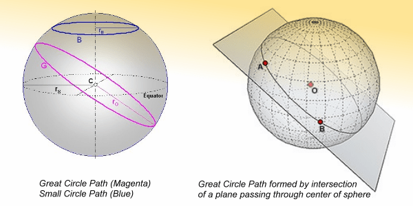
The illustration depicts the concepts of Great Circle and Small circle on the surface of the Earth. Note that the intersecting plane must pass through the center (origin) of the sphere for the surface intercept path to be a Great Circle. A Geodesic Great Circle will always have its radius equal to that of the Sphere.
A straight line path between two points on a flat surface determines the shortest distance between the points. Similarly, the Geodesic Path between two points on the curved surface of the spherical earth also represents the shortest possible distance between these points.
If you have access to a Globe (used in school geography classes), or any convenient sized spherical object, then try to check it out for yourself. Take a string or an elastic band and stretch it between two distant points on the surface of the globe. If possible, use a tack pin to secure the string at the first point. Hold the string taut at the second point and gently pluck it while lightly pulling the string at the second point. The string would naturally take the shortest path between points. This will be the Geodesic Path.
If we were to extend a geodesic line beyond the two points on a flat surface, they would extend indefinitely on either side. However, on a spherical surface, the extended Grodesic line would circle around the spherical surface and return back to the point of origin. In other words, a Geodesic Line on the surface of the earth will produce what appears to be a circle drawn around it. This circle is called the Great Circle.
The Great Circle (GC) is not just any arbitrary circle drawn on the surface of the earth. It has several interesting geometric properties. The Great Circle drawn through any two points on the earth is unique. There cannot be more than one Great Circle that could be drawn between a set of two points. The Great Circle unambiguously determines the only possible (single) radio signal propagation path between two radio stations. The radio signal will not propagate along any other path other than the Great Circle path.
At this point, some might ask, how about the Short-path (SP) and Long-path (LP) in HF radio communication? Doesn’t it mean that not one but two unique paths might be available? NO! That’s not entirely true… We must not confuse ourselves between geometric paths and directions. In the case of both SP and LP between stations, the path is the Great Circle which is common. The difference between SP and LP is therefore not the path but the direction of travel or propagation. Both SP, as well as LP, follow a singular and unique Great Circle path between the two stations.
There is only one exception to the above-cited geometric singularity rule for Great Circle paths. This exception occurs if the two DX stations in communication are located at Antipodes. If both the radio stations are located at places that are diametrically on the opposite side of the spherical earth, then they are termed as being located at each other’s antipode. Typically, if the other station is at one’s antipode, then the distance to that station will be half the circumference of the earth (approx. 20000 Km). Being halfway around the circumference, the distance to the antipode will be identical irrespective of the beam-heading along the Great Circle path. Hence, an antipode will not have distinctive SP and LP. They will be the same.
Most importantly, the uniqueness of an Antipode is that, unlike a single Great Circle that would pass through any two regular sets of two points on earth, there could be innumerable Great Circle paths between two stations located at each other’s antipode. Any Great Circle path that could be drawn from a station along any azimuth direction, or along any Great circle vector will always pass through the Antipode. To learn more about antipodes, read the article on Challenges of working HF DX near Antipodes.
So far, we have examined the basic intuitive concepts related to Geodesic Paths and great Circles. Let us take a brief look at the geometric aspects so as get a better insight and also prepare ourselves to learn how these paths might appear on regular 2D maps that we commonly use. Some of us might also be wondering as to why we call it a Great Circle path when it actually determines the shortest path between locations? Let us find out…
One can draw countless circles on a globe. Some of them might have a large diameter while others might have smaller diameters. Circles can be drawn at any location on the globe at any surface inclination. However, the largest circle that could be drawn would have a diameter equal to the diameter of the sphere (globe). Any larger-diameter circle will not lie on the surface but would at least partially be outside the spherical surface. Hence, a circle with a diameter equal to the sphere’s diameter is the greatest sized circle that could be drawn on its surface, it is called the Great Circle. All other circles having diameters smaller than the diameter of the sphere when drawn on the surface are called Small Circles.
There are a few important and unique properties of a Great Circle that are relevant to radio communication and the associated Geodetics related to signal propagation paths. Let me list some of them below…
- The center of a Great Circle drawn on the surface must coincide with the center of the sphere.
- In other words, a Great Circle is produced by an imaginary intersecting plane that passes through the Origin of the sphere. The points of intersection of the plane and the sphere’s surface form the Great Circle.
- The surface distance between any two points on a Great Circle is the shortest possible distance between them. Radio waves, unless acted upon by extraneous factors, will travel along the Great Circle path without deviation.
- Only a single (unique) Great Circle can pass through any two points on the surface of the earth (spherical surface). The only exception is when the two stations (points) are located at antipodes.
- Any other path between two points except for the one along the Great Circle will have a longer physical distance.
So far, we have touched upon the fundamentals of Geodesic Paths as perceived on a near-spherical surface like that of earth. Based on this, I believe that the basic concepts must be reasonably clear by now. It is relatively easy to visualize a Geodesic Path and a Great Circle on a spherical surface. However, when we translate the spherical surface of the earth on a point-to-point basis through cartographic projection onto a 2D planar surface, the visualization of Geodesic Paths might become less intuitive… We will take up the map projections in a moment but let us first summarize some of the implications of radio signal propagation along Geodesic paths.
Implications of Geodesic Paths on long distance radio communication
An alert reader who might have been following this narrative carefully will realize that the notion of the Geodesic path appears to be logically true when applied to direct wave (LOS) terrestrial communication as in the case of VHF/UHF point-to-point circuit.
However, one might ask, how can HF skywave skip propagation follow a Geodesic path? After all, isn’t it true that the propagating signal bounces back-and-forth between the ionosphere and earth as it progresses?
Very true! The radio wave indeed moves forward while skipping within the bounds of an intangible duct formed between the earth and the ionosphere but the overall geodesic direction of forward propagation remains straight and undeviated. Hence, from the terrestrial propagation perspective, the radio wave is deemed to follow a Geodesic path along the surface of the globe.
- The effective forward direction of signal propagation for terrestrial radio communication is along the curvature of the earth. This is despite the fact that the propagating signal might encounter other phenomena like ionospheric skip, tropospheric super-refraction, ducting, etc.
- In the case of VHF/UHF terrestrial radio, typically due to short communication distance, the effect of an extremely small amount of earth’s curvature encountered is rather negligible. Hence, most terrestrial VHF/UHF communication circuits may easily be indicated as straight lines on a 2D geometrical surface (map).
- As the length of the communication path across the globe increases, the geometric effects of the earth’s curvature become significant. The propagation path is now greatly influenced by 3D spherical geometry and hence follows the Geodesic Path over the surface. These Geodesic effects play prominent roles in HF radio communication.
- The Geodesic signal propagation Path over the surface of the earth is always along a Great Circle. Hence, we call it the Great Circle path.
- Any set of two geographic locations on earth will have a unique Great Circle passing through them. This path, after passing through the two locations extends along the earth’s circumference to complete the Great Circle. Hence, the two points (radio stations) on the circle determine two arcs (segments) of the circle. One arc segment may be shorter in length while the other might be longer. The radio signal might travel along either the shorter arc or the longer arc. The shorter arc is called Short-Path (SP), while the longer arc is called Long Path (LP).
- Both the SP and the LP fall along the Great Circle path. Geometrically, both of them are equally viable radio communication paths. However, due to the shorter distance of SP, the radio propagation prospects typically favor this path. On the other hand, LP propagation openings are usually far more rare and elusive. Whenever there might be an LP propagation opening, both the stations can swing their beam antennas around by 180° in the opposite direction from their regular SP headings to conduct a QSO.
- The SP distance is always less than half the circumference of the Great Circle (~40000 KM). Hence, SP is always less than 20000 Km, while the LP is always between 20000-40000 Km.
- A unique case of the above is when the distance between the two locations is equal to half the circumference of the Great Circle (~20000 Km). In this case, there is no distinction between SP and LP. Both distances are the same. The DX location that fulfills this condition by being located exactly halfway around the globe along the Great Circle path is called the Antipode.
- When two stations are located at Antipodes of one another (~20000 Km), then it results in a unique geometric property. Unlike all other situations where only one unique Great Circle can pass through them, the radio stations at Antipodes may have an unlimited number of great circles that could pass through them. This would geometrically imply that radio signal could travel along any direction across the surface of the globe, yet it would reach the destination station at the Antipode.
- Despite the above-cited geometric condition between the Antipodes, signal propagation would never really occur over all the great Circle paths along various azimuths in the case of practical HF radio communication scenarios. HF skywave propagation depends on several ionospheric properties that may favor communication only along a preferred direction (path) at any point in time and a specific frequency band. Propagation conditions along other geometric Great Circle paths (azimuths) would usually remain unfavorable.
This brings us to an interesting spherical geometry phenomenon. We now know that any two Geodesic Paths originating along with the different azimuth angles from any location will naturally diverge as they propagate along the surface of the earth. Well, so far it is quite intuitive. However, from our bulleted points list above, we also know that they must converge at the Antipode. This last bit may not be so intuitive… One might ask, How can that be? After all, the radio waves travel along straight lines along Geodesic Paths. By definition, Geodesic Paths are straight lines. Aren’t they? How can diverging straight lines converge at a point? Isn’t it a dichotomy?
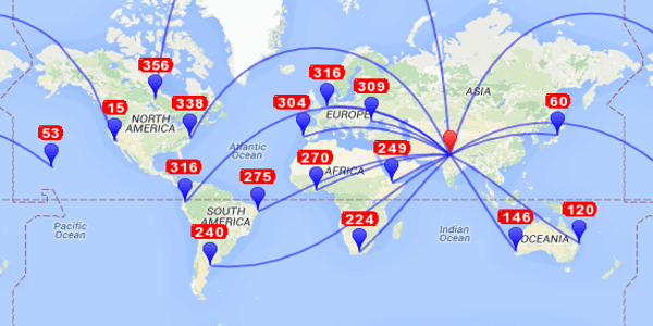
A typical depiction of Great Circle Geodesic paths (shortest distance between locations) plotted on a 2D map. The illustration shows my (VU2NSB) QTH at ML88nr as the origin with paths drawn to various locations around the world. Note how the shortest length, straight-line geodesic paths appear as curved lines on a map.
By virtue of this property, the two diverging (Geodesic) paths that originate from a point on earth will have to converge and pass through the Antipode. Therefore, the initial progressive divergence between the two paths has to stop somewhere down the path. After this point, the paths must start converging to eventually intersect at the antipode. This transition from divergence to convergence will occur at a point that is halfway from the Antinode. This would be at a distance of 20000/2 = 10000 Km.
Therefore, in the case of HF terrestrial radio communication, the transmitted radio signal energy from the antenna in various directions around the azimuth (as determined by antenna beamwidth) will initially continue to diverge as it propagates, thus providing wider coverage areas at progressively greater distances. As the beam spreading due to divergence happens, the reduction of the power density of the signal at distant locations also happens. The RF power-density reduction would occur until a distance of ~10000 KM from the transmitting station. As the distance to the RX station increases beyond ~10000 Km, the two azimuth boundary edges of the antenna beam begin to converge. The effective beamwidth along the earth beyond ~10000 Km begins to reduce. As a consequence, the RF power density concentration once again begins to increase. This process continues till the Antipode is reached where the antenna radiation beamwidth converges totally. Of course, as the radio wave propagates beyond the Antipode along its journey over the Long Path (LP), the beam begins to diverge again.
After reading the above, one might begin to believe that on account of the beam convergence beyond 10000 Km, the HF radio signals would become far stronger beyond 10000 Km. Unfortunately, that’s not entirely true. The aggregate path losses in HF terrestrial radio communication is determined by several more influential factors related to the characteristics of the prevailing ionospheric conditions. If the signal attenuation were only to be dependent on the principles of free-Space Path Loss (FSPL) as determined by the Friis Transmission formula, then the converging beam could have strengthened the signal. However, that is not the case. The effects of ionospheric attenuation are far more dominant and decisive factors in determining the aggregate HF radio propagation losses.
Having said that, the positive influence of signal power density boost due to beam convergence does not go entirely in vain. It helps in providing some degree of enhancement. Under favorable conditions of ionospheric propagation, the influence of beam convergence certainly does play a small contribution towards a stronger signal at the receiver.
Commonly used 2D Map Projections and their application in amateur radio
So far, in our discourse on Geodesy for terrestrial radio communication, we have discussed various properties based on the natural 3D spherical globe model of the earth. Although the globe represents the true physical shape, in our day-to-day life we more often tend to use 2D geographical maps. Therefore it is important that we learn to properly correlate the concepts of Geodesic paths and distances to 2D map implementations.
As amateur radio operators, we too need to familiarize ourselves with some of these different types of maps and their implications in relation to Geodesic Paths for radio propagation. Apart from the typical Rectangular 2D maps, we also find the Great Circle map of great use in radio communication. There are dozens of major different types of Map Projections with each type having several sub-variants. This leads to hundreds of map types.
A Map Projection is the transformation of Earth’s curved surface (or a portion thereof) onto a 2D flat surface by means of mathematical equations. During such transformation, the angular geographic coordinates (latitude, longitude) referencing positions on the surface of the Earth are converted to Cartesian coordinates (x, y) representing the position of points on a flat map.
Intuitively speaking, let us imagine that there is a highly stretchable, flexible, thin latex rubber layer clinging to the surface of the globe with all geographic entities like continents, oceans, etc printed on it. Now, let us carefully cut the latex layer with a sharp knife from one side and peel it off the surface of the globe. If we stretch the peeled latex layer and paste it on a flat surface while ensuring that this peeled skin is stretched into a perfect rectangle, then we have a map. The peeled-off latex skin will require considerable horizontal stretching near the top and bottom to make it rectangular. Remember that every bit of stretching that we needed to do to paste it into a 2D map would result in distortion.
Since all maps are projections of the 3D spherical earth onto a 2D canvas, no map in the world is perfect. They all introduce one or more types of distortion. Different types of map projections introduce different types of distortion while preserving one or two key properties. Different map projections will preserve either area, forms, distances, or directions by keeping that specific property free of distortion. However, other than the preserved property, the rest of the features may get distorted. This is the reason why we have so many different types of map projections, each suited for a specific application.
Thankfully, we radio amateurs need not worry about all map variants. However, we should acquire a minimum understanding and working knowledge about a few of them. In this article, I will briefly introduce you the following types of maps.
- Orthographic Projection
- Cylindrical Equal-Area Projection
- Cylindrical Equidistant Projection
- Cylindrical Conformal Projection (Mercator Projection)
- Azimuthal (Zenithal) Projection (Great Circle Map)
As radio amateurs, our main concern is to determine and trace the Geodesic Path of radio propagation between any two distant locations on earth. We might like to draw this path either on a physical or a digital map. We might also like to draw the antenna beamwidth flare-out across the map to ascertain the antenna beam coverage area at DX distances. All such Geodesic projections can be made on each of the above-listed map types but they might look different on different maps. Some common map types may appear to be more intuitive and user-friendly while some others might not. Yet, despite some of these map types being slightly less intuitive as maps, they may turn out to be far more intuitive at displaying and projecting antenna beam-heading, Geodesic path, radio area coverage, etc… We will find out more about this as we progress through this article.
At first sight, most of these different types of maps might look pretty similar. However, on a closer look, one would find several noteworthy differences. Some of the differences may be subtle but they may have implications. We, the radio amateurs, typically need to plot the Geodesic propagation path for HF radio DX, sub-satellite forecast paths, or the satellite coverage area footprints, etc. Although most types of rectangular maps are capable of serving our purpose, some of them are better suited than others. We need to understand these differences.
Let us examine each of the above cited map projections one by one.
Orthographic Map Projection
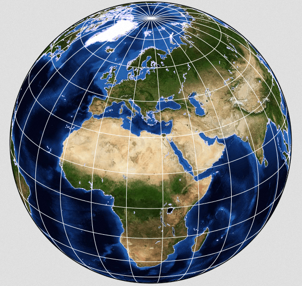
An Orthographic map projection. Multiple maps are needed to cover the entire surface of Earth since each Orthographic map can cover no more than a hemisphere.
Even though Orthographic map projection introduces considerable distortion at radial distances further away from its center, it provides a fairly good perspective into the actual size of various geographic entities. For instance, a typical Google map (Mercator) shows Greenland to be almost the size of the African continent, however, in reality, it is very much smaller than Africa. An Orthographic projection would provide a far better and truer picture.
In amateur radio, one might not find many regular applications for Orthographic projection, unless one wishes to acquire a better pictorial understanding of some concepts like the Great Circle path, Day-Night Terminator line (twilight zone), orbiting satellite sub-surface tracks, etc. This map projection also provides a very intuitive view of LEO satellite coverage area footprints. You might like to check out on a couple of illustrations depicting them in my article on Earth Satellite Orbits.
Not very many people might be aware of it but another place to find an Orthographic map is in Google Maps. It is more or less a shrouded feature and not so easy to find. Google Maps normally use rectangular map projection that they call Web Mercator, however, they also have an option to project a nearly Orthographic Map type in Earth view at high Zoom-out levels. Google refers to it as Azimuthal Perspective projection. Unlike a true Orthographic projection that is viewed from an infinite distance, Google’s Azimuthal Perspective renders the projection as viewed from finite distances in outer space thus making the projection, not a true hemispherical projection.
Cylindrical Equal-Area Map Projection
This is one of the several types of popular rectangular map projections. The projection was first described by the Swiss mathematician Johann H. Lambert in 1772. Since then, many variations appeared over the years.
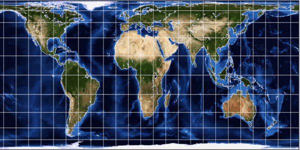
Lambert’s Cylindrical Equal-Area map projection preserves the sizes of various geograhic features and entities. However, the shapes and distances get distorted.
I have explained in the earlier part of this article how the virtual canvas (peeled skin of the globe) needs to be stretched quite significantly at higher latitudes, especially near the poles to produce a 2D rectangular map. Please also revisit and take a closer look at the map canvas creation animation above. You will notice that the lines of longitudes that converge at the north/south poles on the globe become parallel lines (meridians) on a rectangular map. As a consequence of this horizontal stretching, the width of geographic entities at higher latitudes becomes much more than what they are in reality.
Due to the above reasons, the areas of landmasses, oceans, and other geographic entities at latitudes progressively further away from the equator start becoming disproportionately large. Therefore in the Equal-Area Map projection, we have to find a way of reducing the disproportionate areas back to normal. Since the longitudes must remain parallel to one another, the only way of doing this is by plotting the latitudes progressively closer to one another as we move from the equator to the poles. The net result of this exercise is that entities at higher latitudes on either side of the equator begin to appear compressed along the longitudes.
Check out the accompanying illustration of the Equal-Area Map projection. One would notice that entities like Greenland, Scandinavia, etc appear quite flattened. The shapes of entities near the poles are distorted but the sizes are not. This map projection shows various countries, continents, and water bodies as per their true relative sizes. Although from a cartographer’s perspective, despite shape distortion, an Equal-Area Map has unique value because it enables realistic evaluation of areas of geographic entities, this map type may not be ideal from a radio amateur’s perspective.
Even though the relative size of various countries are correctly and proportionately depicted on an Equal-Area map, for us the radio amateurs, it becomes rather inconvenient. Entire Europe, especially UK, Scandinavia, Benelux, etc appear small on this type of map but these places are important because of areas of large amateur radio operator density. Hence, some other type of map projection that could display Europe a bit bigger would be preferred.
Cylindrical Equidistant Map Projection
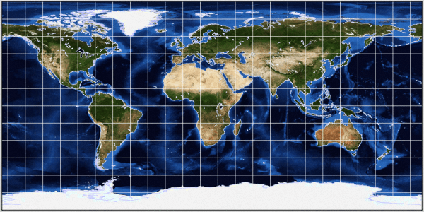
A typical Cylindrical Equidistant (Equirectangular) map projection which is the simplest form of a map with equally spaced meridians and parallels. However, this type of map neither preserves size, nor shape, nor direction of navigation.
All the meridians and parallels (longitudes and latitudes) are projected with equal spacing on the map. Due to the equal spacing of parallels, the compression effect that we witnessed in the case of Equal-Area maps does not occur in this type of map. Both Europe and Greenland appear much larger (though incorrectly) and therefore makes this map more convenient to use.
Several amateur radio software, as well as literature with map illustrations, use this type of map. Of course, one might far more frequently come across Mercator maps (covered in the next section) and to a much lesser extent the Lambert’s Equal-Area maps, the Equirectangular map is a good choice. The Equirectangular map embodies characteristics that are perhaps the best of both worlds. On one hand, it does not compress the geographic features at high latitudes, while on the other hand, unlike Mercator map, it successfully projects (without clipping) the full surface of the globe between ±180° longitudes and ±90° latitudes… More on that later when we discuss Mercator maps.
As a consequence of the above properties, the Equirectangular map is perfect for most amateur radio applications. All geodesic paths for radio propagation as well are satellite footprints, etc will all fall entirely on the map canvas and hence can be drawn on it without clipping off parts of either the geodesic lines or footprint boundaries which are quite common in the case of Mercator map.
It is fairly easy to identify an Equirectangular map and distinguish it from an Equal-Area map. In the case of the Equirectangular map, all lines of latitude will be equidistant from one another, whereas, in the case of the Equal-Area map, the latitude lines will progressively come closer to one another near the higher latitudes and polar region.
Cylindrical Conformal Map Projection (Mercator Projection)
Cylindrical Conformal Projection is also referred o as Orthomorphic Projection. The well-known Mercator Map is a typical map projection of this kind. This is one of the most popular map projections that is found in day-to-day use. For use in radio communication applications, I would personally prefer the Equirectangular map to the Mercator map most of the time.
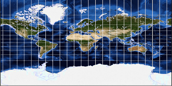
A Mercator map is a cylindrical conformal projection whereby it preserves the directions and angles on the nap even though the size of geographic entities are grossly distorted.
What is a Mercator map? What is a Conformal projection? What is so different about this type of map to make it a preferred choice for Google? Let us answer these questions one by one before we dig deeper.
There are both downsides and upsides to a Mercator map. The biggest downside is that it provides a very highly distorted view of the world where the sizes of geographic entities at higher latitudes, especially near the Arctic circle are greatly exaggerated. For instance, in a Mercator map, Greenland looks as large or even bigger than the continents of Africa or South America. Similarly, countries in Europe, as well as places like Alaska, appear to be disproportionately large. These exaggerated sizes of certain regions of the world are absolutely false. To get an idea of the actual sizes of various geographic entities, check out Lambert’s Equal-Area projection.
Before I explain why Google chooses to use Mercator maps, let us first answer the other two questions… What is a Conformal projection? What is a Mercator map?
Conformal map projection is a 2D projection of the spherical earth’s surface whereby we preserve the directions between places on the map without distortion. I had stated earlier that out of various features of a map like size, shape, direction, etc of geographic entities, a typical map projection can preserve only a few parameters while it would distort the rest. This is why we have so many different types of map projections, each with the objective to cater to different applications. For instance, Lambert’s Equal-Area map that we discussed earlier preserves size at the cost of other parameters. Similarly, Conformal projections persevere directions and shapes while compromising and distorting other parameters including sizes.
Please note that while these maps preserve the shape of geographic entities but not their size. Hence, these maps are disproportionate and heavily distorted, especially above the mid-latitudes.

A depiction of typical Rhumb Line (Loxodrome) and a Great Circle Geodesic path (Orthodrome) on a Mercator map. The Great Circle path is the shortest path between locations but direction angles continuously change along the path whereas the Rhumb Line is a longer path but the direction angle of navigation remains constant.
It might appear paradoxical but it is true that although the Rhumb Line (loxodrome) which appears as a straight line might seem to be the shortest distance when viewed on a 2D map is actually longer if projected back onto the surface of the globe. On the other hand, the Great Circle path (Orthodrome) that seems to be much longer in length due to its map rendition as a curved path is, in reality, the shortest distance path on the spherical globe. Remember, all rectangular 2D maps produce huge amounts of distortion in shape, size, and distances which results in various kinds of peculiar visual illusions.
Mercator map is the most popular and widely used variant among several others that qualify as Cylindrical Conformal Projection. Google Maps has also chosen to use Mercator maps. They call it Web Mercator. The question is, Why? Why couldn’t they choose another type of map? The answer is logically rather simple…
One of the major target applications of Google maps is to provide street-level navigation and driving directions. Street-level views of cities all around the world are provided to the users. Since the Mercator map (Conformal projection) do not distort directions and angles on the map irrespective of the location at any latitude or the zoom level of the map projection, it is best suited for serving the primary objectives of Google Maps.
Let us finally examine the implications of using a Mercator map in amateur radio applications. Frankly speaking, there are no major adverse implications. A Mercator map is perhaps as good as any other and serves our needs perfectly well. However, on account of various unique properties of any type of map projection, they may present minor anomalies.
What is the single most unique feature of the Mercator map? It is the preservation of directions, angles, and shapes of paths and objects on the map. To achieve this, the spacing between the latitude lines (parallels) is progressively increased at higher latitudes. This is done to proportionately match and compensate for the horizontal stretching of the map canvas at higher latitudes to make the longitude lines (meridian) parallel to each other. The proportionate expansion of map canvas size horizontally (across longitudes) and vertically (across latitudes) results in bloating up the sizes of geographic entities in the upper latitudes regions of the earth, however, at the same time, it also ensures that the directions and angles on the map are preserved.
On account of the above-cited stretching of the map at higher latitudes, we run into a problem. Due to the exponential nature of the increase in spacing of latitude lines, it becomes impossible to plot the highest latitudes near ±90° region near the north/south poles on a Mercator map. Mathematically, it would be impossible to plot the geographic poles on this type of map because the map canvas would need to be stretched vertically to infinity on either side. As a consequence, a practical Mercator map like the Google Map only displays regions within ±85° latitude boundaries. All regions of the earth above and below the ±85° latitude boundaries are clipped and not displayed.
For radio communication-related applications, it has a few implications. Due to the vertical outward stretching of the parallels at higher latitudes, the displayed Great Circle paths on a Mercator map tend to have a larger curve. Secondly, any Great circle propagation path over or near the polar region (passing above ±85°) will get cropped and cut at the top or bottom thus displaying a path discontinuity on the map. In the case of satellite footprints and sub-satellite tracks too, the above-cited cropping effect will occur. On the other hand, the map projections like Lambert’s Equal-Area map or Equirectangular map will display all these paths in their entirety without clipping or cropping.
Azimuthal (Zenithal) Map Projection (Great Circle Map)
This map projection produces a very important type of map from a radio amateur’s perspective. Most seasoned amateur radio HF DX operators are familiar with this map and have perhaps used it extensively for finding direction antenna beam heading into the DX land. Nowadays, computers have simplified so many things including the calculation of beam headings over Great circle paths. However, during the earlier days, a Great Circle map (Azimuthal map) was quite indispensable.
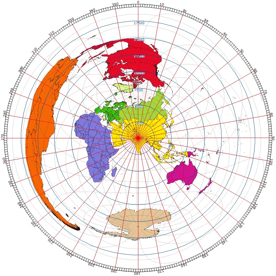
A great circle map (Azimuthal projection) is an HF radio operator’s greatest friend. Although the locations and shapes of geographic entities might not initially appear to be intuitive but after a little practice, it becomes fairly simple. This type of map is excellent for determining antenna beam headings and area coverage of the beam.
The Great Circle map is not a rectangular map but a circular-shaped map. Unlike the rectangular maps that are general and applicable for use by a person situated at any location in the world, the Great Circle map is a location-specific map with the map projection centered around a specific pre-decided location. Therefore every amateur radio operator living at a different geographic location would need a unique Great Circle map that is plotted with the geographic coordinates (Latitude and Longitude) of his QTH as the map center. This is called the Map Aspect. My Great Circle map aspect will be based on my QTH’s location coordinates and hence would be entirely different from someone else’s map aspect.
Unlike the regular rectangular maps that are generic, the Great Circle map has to be custom plotted for a user based on his specific location. However, this is not a deal-breaker. Plenty of free software, as well as web-hosted online services, are available that allow one to plot and download a Great circle map image centered around any custom location. A typical example of a Great circle map that most of us have seen yet might never have given it a second thought is the United Nations Organization (UNO) logo that we see everywhere but rarely notice. The UNO logo is a Polar Aspect Great Circle Map where the North Pole is the map center.
I would sincerely suggest that anyone who might be new to amateur radio but would like to attain proficiency in matters related to radio signal propagation paths in relation to long-distance terrestrial communication must get himself a Great Circle map for his location and thereafter study it carefully. there is a lot to be learned from a Great Circle map.
There are two prominent variants of a Great Circle map. They are the Azimuthal Equidistant projection and the Azimuthal Equal-Area projection. both the variants are suitable for our use. The azimuthal Equidistant projection displays the DX regions near the antipode with lesser size distortion but the central part of the Great Circle map appears to be slightly cramped. On the other hand, the Azimuthal Equal-Area projection expands the central part of the map a bit thus making the geographic features bigger but the features near the outer edge of the circular Great circle map represent the places near antipode get more cramped. The choice between these variants is entirely subjective and I would leave it up to the individual to decide which one to use.
A Great Circle projection irrespective of either variant, invariably preserves the direction from the central point in the radial directions. However, the Equidistant version also preserves the distance integrity while the Equal-Area version would preserve areas of geographic objects instead of distance. The scale is true only along straight lines radiating from the center of the map.
Either variant of the Great circle map would always indicate along straight radial lines from its center, all regions of the world that would be covered by antenna beam heading in that direction. An angle equal to the beamwidth of an antenna from the center of the map in any direction will readily show that areas on the map that could be covered simultaneously by the antenna in that direction. Nothing could be more simple and intuitive than this. However, since we have grown up seeing rectangular maps, initially a Great circle map might appear to be a bit daunting. Spending a little time trying to correlate various continents, landmasses, water-bodies, etc on the Great Circle map to what we already know from the rectangular maps would eventually make it easy to understand.
List of Articles under this Section
The Great Circle Map - GCM The Great Circle Map - GCM We present an automatically rendered Great Circle Map - GCM based on your location derived from your Internet IP address. Therefore the Great Circle Map generated below should be accurate and relevant...Antenna Bearings - Geodesic Map Antenna Bearings - Geodesic Map We present automatically rendered Antenna Bearings with Geodesic Paths projected on a Rectangular Map. Each geodesic great circle path displayed on the map...


(15 votes, Rating: 5.00) - Please vote the article with your valuable star rating. Thanks! Basu (VU2NSB)


SSN SSNf(10.7) – Real-time Solar Data