Search Results
Earth Satellite Orbits
The fundamental nature of Earth Satellite Orbits Satellites have been there enhancing radio communication for several decades. An understanding of Earth Satellite Orbits is crucial to optimizing the use of communication satellite resources. Radio amateurs were quick to start using satellites for communication. Since the early 1970s, serious efforts were made to put amateur radio on the satellite map. Most earth satellites for amateur radio have been placed in Low Earth Orbit (LEO) with some of them being in sun-synchronous polar orbits. I have been actively working through amateur satellites ever since the early days of OSCAR-6 and OSCAR-7 while I was in engineering college… There have been a few exceptions to the LEO satellites for amateurs. For instance, OSCAR-9, 10, and 13 were phase-3 satellite originally designated as P3A, P3B, and P3C respectively. They were meant to operate in a highly elliptical orbit with a high apogee to perigee ratio. Typically the apogee was planned to be around 36000 Km with the perigee around 2500-4000 Km. OSCAR-9 suffered a launch failure while OSCAR-10 was a partial success. OSCAR-13 did... Click Here to Read Full Article […]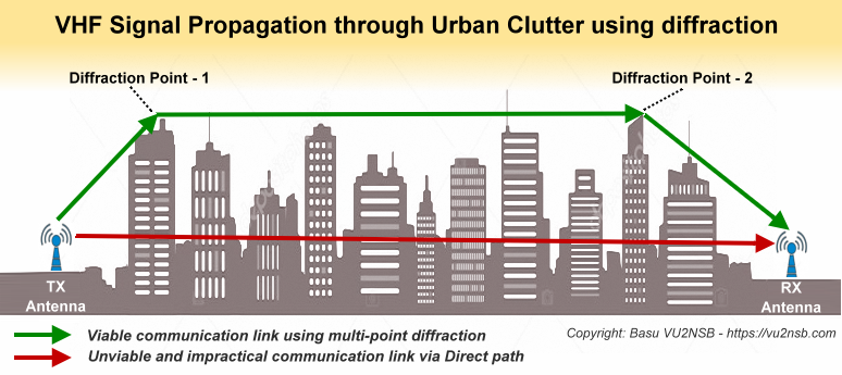
Terrestrial VHF Radio Signal Coverage – LOS
Terrestrial VHF Radio Signal Propagation – LOS Though VHF/UHF radio is very popular, why do the terrestrial VHF radio signal coverage losses grow quickly to curtail the useful range to short distances? This is an important question that needs to be addressed, especially, because quite often it leads to a bit of confusion amongst many radio amateurs, who tend to incorrectly believe that VHF-UHF communication range capabilities are inherently limited due to the nature of propagation losses at these frequencies. This is far from the truth. For instance, satellite and deep-space communication over thousands or even millions of kilometers is conducted on the VHF-UHF or microwave bands… Please note that in the course of the narrative, in this article, I would mostly use the phrase “Terrestrial VHF Radio Signal losses” or “VHF Signal Losses” which would usually imply both VHF and UHF even though I may not be explicitly mentioning UHF every time. Amateur radio earth-orbiting satellites of the LEO class are regularly accessed by operators around the world using low-power communication gear that put out a few watts, into... Click Here to Read Full Article […]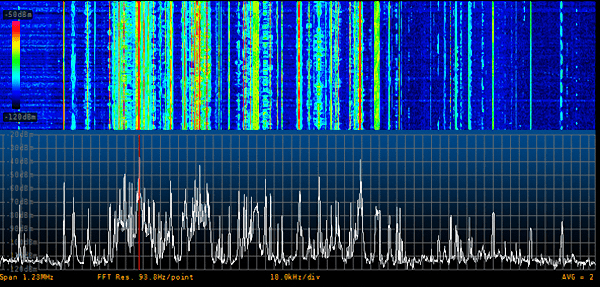
Digital Modulation Fundamentals
The fundamentals of Digital modulation for radio The 21st century has seen a major upsurge of digital modulation methods in radio communication. It is, therefore, imperative for all amateur radio operators to attain a clear insight into some of the essential fundamentals of digital modulation techniques and also to how and why it is done. In this article, I will attempt to walk you through some of the basics and also take a look at the genesis and evolution of digital radio communication. The average radio amateurs who come from various academic backgrounds and may not have an electronic or electrical communication leaning often find it difficult to relate themselves to the stereotypical explanations of the various nuts and bolts of the digital communication model. The objective is to keep this narrative intuitive and simple without dwelling into the associated mathematics as much as possible. Other than the use of digital modulation methods to implement digital voice communication and file transfer of documents, images, etc, the most common digital modulation methods have been used very effectively to implement text mode... Click Here to Read Full Article […]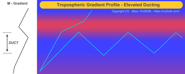
Atmospheric impact on VHF Radio Propagation
Atmospheric influence on VHF Radio Propagation The overall influence and impact of atmospheric conditions on VHF radio propagation are quite significant. In this article whenever I mention VHF, it would usually refer to both VHF and UHF bands. Although the magnitudes of various effects due to atmospheric factors would vary, the pattern of behavior on both these bands would follow a similar trend. The upper part of the UHF spectrum beyond 1GHz leading into the microwave spectrum would of course exhibit distinctively different behavior. Therefore, we will maintain our focus on the atmospheric impact on the VHF and lower UHF band with an emphasis on the amateur radio bands of VHF (2m) and UHF (70cm)… Secondly, when I speak of VHF radio propagation, I would be referring to only terrestrial point-to-point communication and not the earth-space communication. The parameters governing earth-space communication are often quite different. Another important factor to keep in mind is that the atmosphere is a very wide region above the earth extending upwards up to 650-900 Km. Within the atmosphere, there are many sub-regions, of which,... Click Here to Read Full Article […]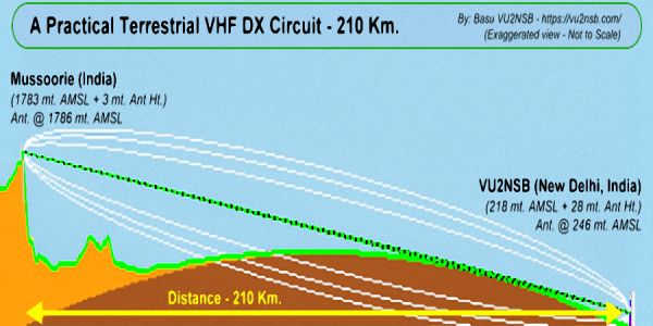
Terrestrial VHF Radio Signal Coverage – BLOS
Terrestrial VHF Radio Signal Propagation – BLOS This is part-2 of the two-part article series on Terrestrial VHF Radio Signal Coverage. This part will focus on Beyond-Line-of-Sight (BLOS) terrestrial VHF radio signal communication, whereas in part-1 we had discussed Line-of-Sight (LOS) communication. To recap what was discussed so far, check out the part-1 at Terrestrial VHF Radio Signal Coverage – LOS. When we refer to beyond-line-of-sight (BLOS) VHF radio communication, we include the non-line-of-sight (NLOS) circuit too. Strictly speaking, NLOS circuits are those which might have been regular LOS path had it not been for some natural or man-made obstacle that came in the way. As per spherical earth geometry, these NLOS paths would be within the radio horizon limits between the two stations. On the other hand, a BLOS communication circuit is essentially beyond the horizon or a trans-horizon circuit. The fundamental difference between the NLOS and BLOS circuit is that in the case of BLOS, it is beside the point whether there may or may not be obstacles in the path in the form of hills, mountains, buildings,... Click Here to Read Full Article […]
Slow Scan TV (SSTV) – How it works
Slow Scan TV (SSTV) – Analog and Digital Slow Scan Television or SSTV is essentially a derivative of the wideband broadcast television system that we are so familiar with. The fundamental principles of SSTV signal structure and modulation are fairly similar to that of the regular TV. However, the primary difference lies in the fact that while the regular commercial television displays motion pictures along with synchronized sound, the SSTV protocol only allows for still pictures to be transmitted over a radio channel. Secondly, picture frame size and resolution are far less for SSTV in comparison to regular TV. SSTV had been conceived around the year 1957-1959. It was inspired by the existing Facsimile system known as Radio-Fax. However, it was not practically suited for amateur radio use over HF radio primarily because of the long frame transmission time required for Radio-Fax which was around 20 minutes. Although the frame resolution of Radio-Fax was high, the long transmit time was rather impractical for amateur radio use. Amateur radio needed to derive a picture transmission protocol that even though might feature... Click Here to Read Full Article […]
Understanding Antennas – The Good, the Bad, and the Ugly
Understanding Antennas – What makes them good or Bad? Are some antennas good while some others are bad? Many people seem to think so, but this notion is not entirely correct. Any such binary black or white classification is not the way to assess antennas. The fact of the matter is that all antennas that have been designed to radiate RF energy efficiently are usually good in their own rights. Yet I concede that the operator’s experience with a specific type of antenna may indeed be either good or bad. However, this does not necessarily mean that the fault lies with the antenna. More often than not it is the operator’s judgment in selecting the antenna or the way it is deployed that makes all the difference. Unless the antenna in question is technically a poor design that does not allow effective radiation to occur or the structural material used for fabricating the antenna leads to high loss resistance in comparison to its radiation resistance, there is no reason why the antenna will not be able to do the job... Click Here to Read Full Article […]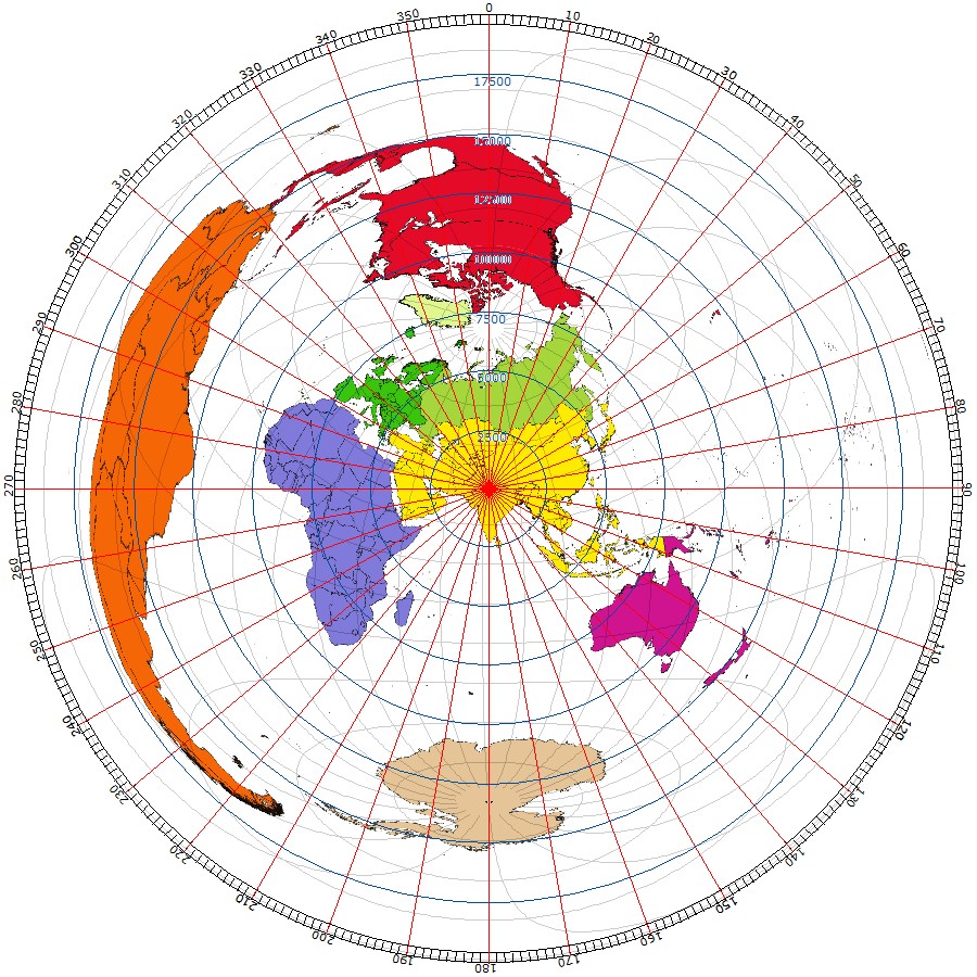
Geodesy for Terrestrial HF Radio
Geodesy and Maps for Terrestrial HF Radio Acquiring a working knowledge of the basic concepts of Maps and Geodesy for terrestrial HF radio communication is important to radio amateurs. The term Geodesy has its origin from the Greek language and is defined as a branch of applied mathematics concerned with the determination of the size and shape of the earth and the exact positions of points on its surface. This brings us to the concept of Geodesic Path in context to a spherical earth geometry. A Geodesic Path is the shortest path between two points on a curved surface, like that of the Earth. This is typically the path that is taken by propagating radio waves from one point to another. However, we must bear in mind that contrary to what some might believe, the earth is not strictly spherical in shape. The earth is slightly flattened at the top and bottom near the polar latitudes that give it a shape that appears to be a little bulged at the equator. This shape is termed as Oblate Spheroid or just... Click Here to Read Full Article […]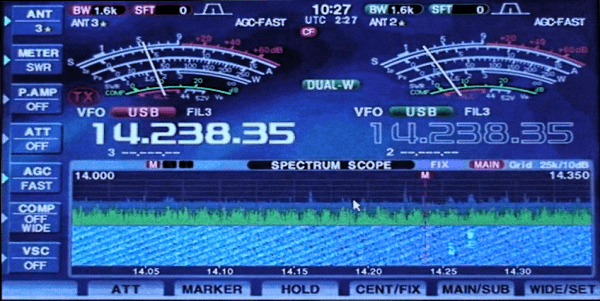
Noise in Radio communication
Introduction to Radio Communication Noise As important as the desired signal, the aggregate undesired noise in radio communication is a factor that is equally important. The insight into the causes and sources of noise are vital to determine a radio communication link feasibility and to determine its capabilities, reliability, robustness, and immunity to failure. Noise in any communication environment may arise from several sources. Therefore, it is imperative to identify and understand each of these noise sources and also to understand their characteristics. After all, what is noise? Is it something characteristically different from the signal? Can the signal be extracted and isolated from the noise by any simple method?… To be able to answer these questions, we need to look deeper into the anatomy of noise. To begin with, the basic composition of radio frequency noise is no different from the radio signal. They are both electromagnetic waves and they both reside in the common passband that is occupied by the desired signal. So, how do we get rid of the noise? The short answer is that WE CAN’T…... Click Here to Read Full Article […]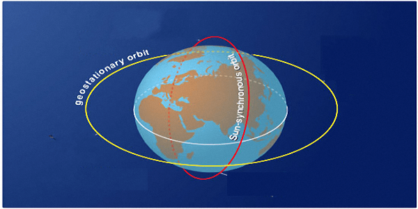
Space Radio Propagation
An Introduction to Space Radio Propagation The propagation of radio waves for space radio communication primarily takes place by Direct wave (a.k.a. Space wave). The space radio propagation could encompass communication between two or more satellites, communication with a space probe in interplanetary space, earth station communication with a spacecraft, communication between an earth station and an earth-orbiting satellite. The satellite-based communication link may be one-way like in the case of telemetry, or more often it might be a two-way link used either for command, control, or for voice, data, and other modes of information exchange. Normally, there are not many geographic entities or man-made artifacts that come in the way of the propagation path to alter the direct space wave propagation characteristics. However, most earth station based space radio communication scenarios involve using earth-orbiting satellites to form a broader communication infrastructure. In this article, we will primarily focus on two-way communication between an earth station and an orbiting satellite. This type of communication system usually operates in the VHF, UHF, or microwave frequency spectrum. The orbiting satellites may have... Click Here to Read Full Article […]
(17 votes, Rating: 5.00) - Please vote the article with your valuable star rating. Thanks! Basu (VU2NSB)


Ham Rig Reviews Coming Soon
SSN SSNf(10.7) – Real-time Solar Data