Search Results
Radio Propagation Forecasting
Radio propagation forecasting and assessment With the advancement in technology over the last few decades, we have made giant strides in Radio Propagation Forecasting and Assessment techniques. The highly volatile and variable nature of HF terrestrial radio propagation has always driven us to find more and more accurate means of predicting propagation conditions. Both long term and short term forecasting methods have improved over the years. The VHF and UHF DX communication also faces several challenges of variability, however, the effects are mostly on account of atmospheric phenomena. Prediction of most of these atmospheric variables with reasonable accuracy still remains quite a challenge. When we speak of forecasting and assessment with reference to HF radio, they often mean two different things. Assessing HF radio propagation conditions to plan radio communication has been in vogue for a long time. Various methods have been used by both professionals as well as radio amateurs. One of the cornerstones of long-range HF propagation assessment has been the time-tested method of using radiofrequency beacons. On the other hand, propagation forecasting is more a science-based on... Click Here to Read Full Article […]
Stacked Antenna Arrays
How do Stacked Antenna Arrays work? Stacked Antenna Arrays or Stacked Array is usually referred to as a set of directional antennas like the Yagi, the Cubical Quad, or the Helical antenna being placed in the vicinity of one another while being driven by a common RF transmitter. This scheme would result in additional forward gain beyond what is available from a single constituent antenna. This is the type of Stacked antenna Array that we are going to investigate in this article. Although, antennas like the Yagi, Multi-element cubical Quad, collinear antennas, etc are technically also antenna stacks. Most of these antennas are created by stacking several dipoles or monopole antenna elements. There are essentially two types of antenna stacks based on their radiation pattern directions. Those antennas which radiate in a direction along the stacking plane of the antenna elements are called Endfire antenna arrays, while those which radiate perpendicular (orthogonal) to this plane are called Broadside antenna arrays. Typical examples of the end-fire antenna array are the Yagi, LPDA, Multi-element Quad, etc. Typical Broadside antenna arrays are the... Click Here to Read Full Article […]
Log Periodic Dipole Array (LPDA)
Log Periodic Dipole array (LPDA) The Log Periodic Dipole Array, popularly known as the LPDA antenna, belongs to a broader family of Log-Periodic antennas. Other than the LPDA, various types of Log-Periodic antenna array structures are available. Some of them are the Log-Periodic Tooth, slot, PCB micro stripline, etc. These variants are most suitable, due to their physical structure, for use at microwave frequencies. The concept of the Log-Periodic array was initially conceived in the year 1958 by two researchers at the University of Illinois in the USA. In this article, we will, however, focus mainly on the LPDA is its classic configuration along with several other offshoot derivatives. The LPDA is used extensively for HF, VHF, and UHF radio communications. The distinctive feature of the LPDA in comparison to other well-known antennas like the Yagi, Cubical Quads, etc is that unlike the other two, the LPDA features a very broad bandwidth characteristic. Physical the LPDA might appear to look more-or-less similar in structure to the Yagi, with multiple dipole elements on a boom with progressively reducing element length in... Click Here to Read Full Article […]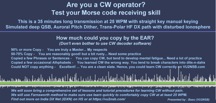
Learn CW Morse Code – Get Started
Learn CW Morse Code – Get Started If you are reading this article, then in all probability you either wish to learn CW Morse Code from the scratch or are one of those who learned it earlier in life but still find it an uphill task to copy CW by the ear. Whichever might be the case, do not fret. We will guide you through the process of mastering CW Morse code with a set of scientifically designed lessons in this section of the website. The method that we employ is proven to help learn CW as if it were another language and not a code. This is the crux of the matter. People often make the blunder of memorizing the CW code set consisting of dits-n-dahs. Never ever do that… Those who are absolutely new to CW will be beginning from the scratch. Hence, they do not carry any baggage of bad learning practices. The others who might feel uncomfortable copying CW by the ear beyond a limited transmission speed because they perhaps learned it the wrong way will... Click Here to Read Full Article […]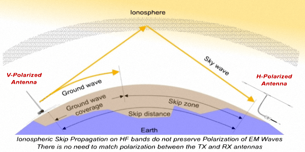
How vital is Antenna Polarization in Radio Communication?
Antenna Polarization in Radio Communication What is the significance of antenna polarization in radio communication? Or, should we ask, how does the polarization of radio waves affect radio communication capabilities? We surely need to understand the fundamental concepts and find out the probable practical effects. By-and-large, most of the antennas that we use on a regular basis are linearly polarized and hence produce linear polarized radiations. Although there are several types of antennas that produce circular (LHCP or RHCP) polarization, they are relatively rare in terrestrial communication application scenarios. Satellite-based radio communication often uses circular polarized antennas both at the satellite and the earth station end of the links. However, that’s a story for another day… Or else, check out the article Amateur Satellite Communications. Moreover, the circular polarization throws up its own set of challenges related to polarization rotation directions. As amateur radio operators, generally engaged in terrestrial radio communication, we normally use linear polarized antennas. This is applicable to both HF as well as VHF/UHF communication. Typically, our antennas are oriented in ways to favor either Vertical or... Click Here to Read Full Article […]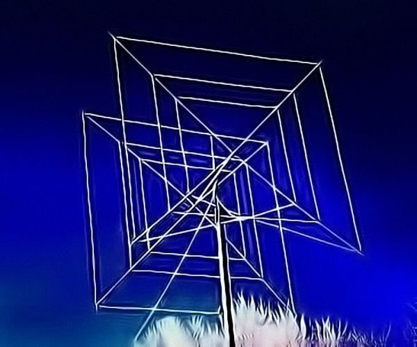
Cubical Quads & Delta Loops
Cubical Quad antennas and Delta Loops When we think of a Cubical Quad or a Delta Loop, the picture that we usually visualize is a large multi-element structure of vertically oriented wire loops on boom and mast with a rotator that swings the structure around. They feature a unidirectional radiation pattern with fine overall characteristics and performance. This is very true for cubical Quad and Delta Loop arrays but all Cubical Quads need not be arrays. We can very well have a single element Quad loop with bidirectional radiation properties. In this article, we will examine the Cubical Quad or Delta Loop geometric structure as antennas. The common term Cubical Quad will be used in general for both type of loop structures. However, specific references to Delta Loop will only be made when it warrants a distinction on account of a unique characteristic or feature. Cubical Quad and Delta Loop Geometry Let us start by examining a single Quad Loop and see how it behaves and what it has to offer, In contrast to a dipole which is 1/2λ in... Click Here to Read Full Article […]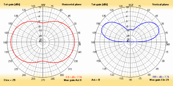
The Ubiquitous Dipole Antenna
The Center-fed Half-Wave Resonant Dipole Antenna The Dipole antenna is perhaps structurally the simplest antenna to fabricate and deploy. It requires a minimal set of hardware components and is quite light-weight. All Dipole antennas need not be single-band or resonant antennas, but its most widely used avatar is the monoband half wavelength (1/2 λ) version. Therefore, in this article, we will focus on the Half-Wave Resonant Dipole antenna and leave the discussion on non-resonant Dipoles to another article. A Dipole may present itself to us as the typical stand-alone antenna, or it might also be a part of more complex antennas, very often playing a role as their core sub-component. For instance, an awesome looking multi-element Yagi or even a Cubical Quad antenna are actually formed out of a combination of a set of Dipole elements… Surprised? Nevertheless, it’s true. A dipole is the core building block of most types of antennas that we are usually familiar with. So, when I say that a Dipole antenna is ubiquitous, I really mean it… Despite its simplicity, the Half-wave Dipole is an... Click Here to Read Full Article […]
CW & Digital
Fascinating world of CW, SSTV and Digital Radio Since the advent of radio communication in the late 19th century, it has made rapid progress in technology over the passages of time. EM waves propagated between two distant locations. Originally it was CW (Morse code) that was used as a method to carry meaningful information over radio waves. Of course, Radiotelephony and Digital Radio modes were developed later. By itself, in its own native steady-state form, EM waves do not carry any information and hence it is not of much use. We need to superimpose information by using cleaver means to ride on the EM waves (Radio Waves). This is accomplished by a process of modulating the radio wave. Therefore the plain radio wave is the carrier (or a carriage like a horse-cart). Unless some cargo (information modulation) is placed on the carrier (the carriage), the whole exercise of radiating and propagating radio waves between two distant locations is pointless. CW and analog radio-telephony speech modulation like AM, FM or SSB played a predominant role during the first 100 years of... Click Here to Read Full Article […]
HamSphere 4
Real vs HamSphere Virtual vs Hybrid Radio communication and Amateur Radio as the terms suggest, clearly define the mode of communication using electromagnetic (EM) radio frequency waves. Hence it is obvious that the medium of signal transport must be able to propagate EM waves and not electrical RF energy. There is a clear distinction between the two. EM wave propagation relies on a self-sustaining propagation mechanism by continuous and alternating transfer of energy between an electric field and an associated orthogonal magnetic field. Each of these energy transfer processes generates a new EM wavelet which continues to propagate. In contrast, electrical RF energy uses an electrically conductive medium like copper wires similar to transporting energy at other frequencies including the well-known utility power distribution networks. We may also use fiber-optic medium by modulating a light source with information which propagates over a graded density refractive index medium within the confines of the optical cable. But this too is not Radio propagation. Virtualization is the process of replicating the behavior of a physical real-world process using mathematical modeling, whereas Hybridization is... Click Here to Read Full Article […]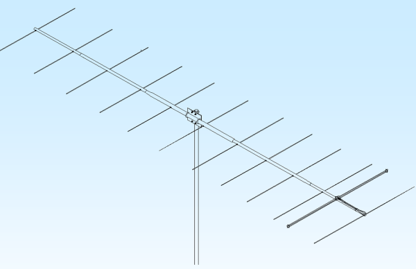
Yagi Antennas
How do Yagi Antennas work? A Yagi-Uda antenna popularly known as the Yagi antenna is perhaps one of the finest inventions ever made in the field of antennas that revolutionized the world of radio communication. In the year 1926, prof. Shintaro Uda and prof. Hidetsugu Yagi of Tohuku Imperial University, Japan did pioneering work and created the concept of beamforming of antenna radiation by utilizing parasitic elements placed in close proximity to the radiating element. This concept was further refined by the work of countless people over the years but this path-breaking antenna structure was dedicated to prof. Yagi and prof. Uda. Hence we have called this type of antenna the Yagi-Uda antenna or more popularly as the Yagi antenna. Perhaps, we all know that a Yagi antenna provides a unidirectional radiation lobe pattern and enhanced forward gain in comparison to a dipole. However, some might ask, what is the unique concept that makes a Yagi antenna tick? What makes it distinctively different from other types of antennas? … Fair question! We will try to examine some of the fundamentals... Click Here to Read Full Article […]
(21 votes, Rating: 5.00) - Please vote the article with your valuable star rating. Thanks! Basu (VU2NSB)


Ham Rig Reviews Coming Soon
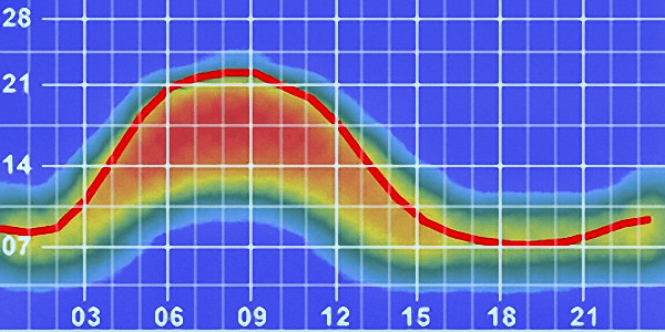
SSN SSNf(10.7) – Real-time Solar Data