Search Results
Ionospheric Skywave Propagation
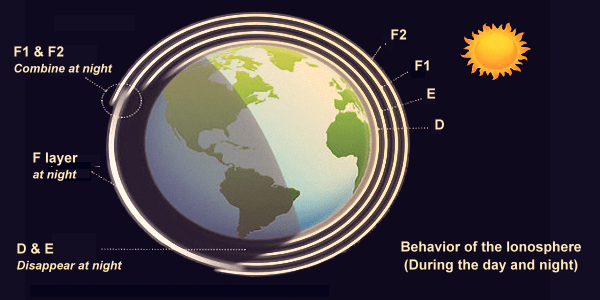
Ionospheric Skywave Propagation – A Curtain Raiser The most important propagation mode for HF radio communication is Ionospheric Skywave propagation. Starting at the bottom of the D-layer and all the way till the top of the F2-layer lie a very wide zone where ionization of gasses in the air occurs. Ionization throughout the entire region is contiguous but follows a varying gradient pattern of ion density. The ionospheric layers D, E, F1, and F2 are the distinct areas of high ionization within the broad region where ionized particles exist. These are the positions at which we have significantly more dense ionization compared to the intervening space. Due to high charge concentration, these ionospheric layers interact with the propagating EM wave and produce unique phenomena resulting in the bending of EM radio waves. For the purpose of simplification, we will, for the time being, ignore the presence of lower density ionization in the inter-layer intervening space and presume each ionospheric layer as distinct ionized entities. Each ionosphere layers (D, E, F1, and F2) have a few common behavioral traits which we... Click Here to Read Full Article […]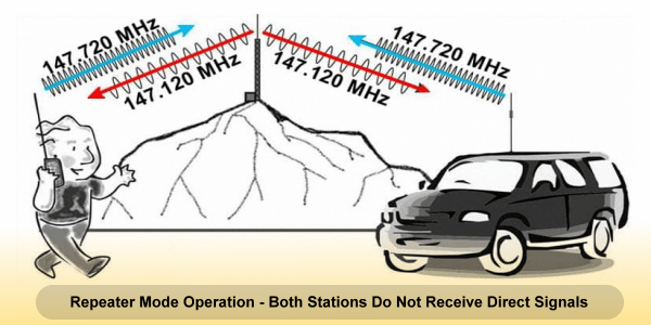
Why doesn’t 59 Signal Report on Repeater make sense?
Does 59 Signal Report on a Repeater make any sense? Does a 59 Signal Report exchange during a QSO on a Repeater make sense? Unfortunately, it doesn’t… We so often come across stations who report 59, or 59+20dB, etc to the other station during a QSO that is conducted through a local terrestrial repeater or during a QSO made via FM repeater type LEO amateur satellites. To top it all, I have come across instances where even a net-controller on an FM repeater net doles out this kind of signal reports to other stations and vice-a-versa. None of this makes any sense… Let’s see why? The RST reporting system comprises of three-digit. They are Readability (R), Signal-strength (S), and Tone (T). This is a typical CW signal reporting format most prevalent on HF radio bands. However, for radiotelephony, the third digit (T) is not applicable, and therefore only a two-digit (RS) report without the (T) is given. This is all good when it comes to regular point-to-point Simplex, Half-duplex, or Full-Duplex mode communication. How about repeater-based QSOs? The first digit... Click Here to Read Full Article […]
To invest in better Radio Rig or better Antenna
Choice between a better Radio or a better Antenna What should I focus on? Should I invest more in a better Radio Rig or a better Antenna? What is it that will provide me better communication prospects and more Dx? These are some of the most common questions that have plagued the minds of new entrants to the hobby of Amateur Radio. Unfortunately, it is equally true that having been swayed by the glamour of well-advertised jazzy-looking modern radio rigs, many of these people have made wrong choices. Only to have learned about their mistake the hard way after having spent a lot of hard-earned money that never really paid dividends as per their expectations. Ironically, even many of the extra-class licensees, in haste to conquer the world, had skipped doing due diligence or ignored sane advice from others who knew. They often ended up making reckless decisions and wrong choices. The answers to the questions that we raised at the beginning are unambiguously clear and straightforward. Yet, at times, amongst a section of radio amateurs, there seems to be... Click Here to Read Full Article […]
Inverted V Antenna – A popular Dipole variant
The Center-fed Half-Wave Dipole Inverted V Antenna An Inverted V antenna is a very popular variant of the standard horizontal dipole. In his article, I will try to bust some of the myths associated with Inverted V and dipoles. Just as a regular dipole may or may not always be of resonant 1/2λ length, an Inverted V too may not always be cut to resonance. However, the non-resonant variety is relatively less common, therefore in this article, I will stick to the 1/2λ resonant Inverted V antenna and leave the discussion on the non-resonant variety to another article. Many people might tend to consider an Inverted V as an antenna of a separate genre with its own unique performance characteristics, but it is not. It is essentially another dipole antenna that is physically oriented in a slightly different manner than a regular one. The performance characteristics of an Inverted V antenna is not too different from a horizontal dipole. Therefore, I will not repeat what we have already discussed in the article titled The Ubiquitous Dipole Antenna. Readers are requested... Click Here to Read Full Article […]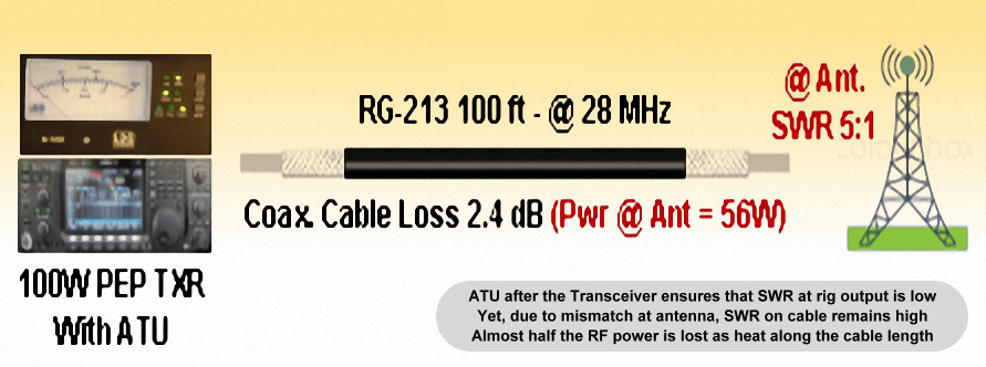
Will low SWR always ensure a good Antenna setup?
Does Low SWR always mean a good Antenna setup? Many amateur radio operators often assume it to be true but the question is, will low SWR always ensure that the antenna has been optimally setup? Although a low SWR on the transmission line to the antenna is certainly welcome, the question still remains whether it conclusively indicates a healthy antenna system setup? contrary to popular belief, No, not always… There are various other factors that go a long way in determining optimum antenna performance. This is notwithstanding the fact that the location of antenna installation, its surroundings, and height above ground play vital roles. Let us ignore these limiting factors because I know that most of us, the radio amateurs, are often constrained by real-estate limitations and therefore may not always be able to install our antennas the way we might have liked to. Within the realms of the above-cited limitations, the SWR is still not the ultimate indicator of antenna system health. Let us examine why is it so, and what are the other factors that could overshadow the... Click Here to Read Full Article […]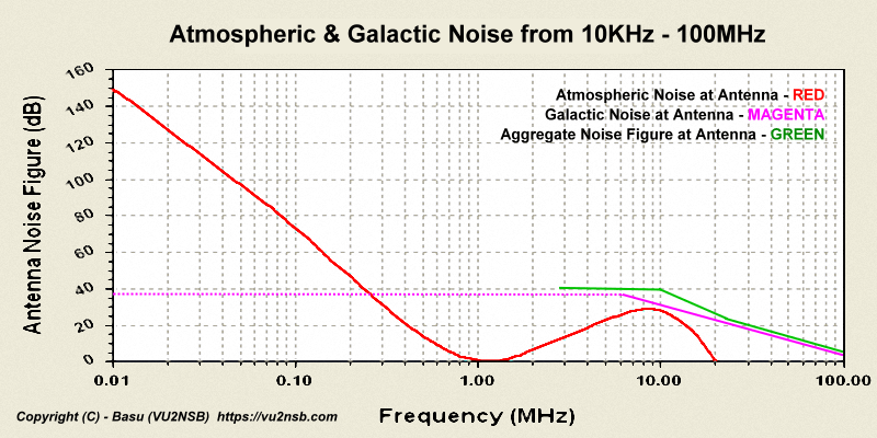
Will High Gain HF Preamplifier help work Weak Signal DX?
High Gain HF Preamplifier for Weak Signal DX? Is it true that a high gain HF preamplifier will enhance the ability to work weak signal DX stations? Broadly speaking, the answer is NO! it won’t. However, for operation on VHF, UHF, and microwave bands, a good low noise preamplifier surely becomes important under most circumstances, for HF bands it is a different story. Though an experienced HF radio operator knows this too well, there are quite a few people who have a false notion regarding this. On various amateur radio forums, Facebook groups, as well as during personal interactions I have come across people who believe that adding a preamplifier to their HF radio rigs might improve their weak-signal DX prospects. Let us try to examine why such a notion is unsustainable and incorrect. We will also briefly examine why a preamplifier makes sense for VHF/UHF or microwave. What is it that sets HF apart from the higher frequency bands? Recap of Noise levels in Radio Communication Environment The prevalent noise levels in a communication system environment determine the limit... Click Here to Read Full Article […]
Space Radio
What is Amateur Satellite Radio? Amateur satellite radio space communication is by-and-large related to conducting two way QSO between stations at distant geographic locations using earth-orbiting satellites which are usually dedicated to amateur radio use. Historically, this started in 1961 with the launch of OSCAR-1 amateur satellite in low earth orbit. Since then there has been an evergrowing interest among the ham community to venture into satellite radio communication. Some of the earlier amateur satellites which became quite popular were OSCAR-6 and OSCAR-7. At present, the amateur satellites consist of those featuring either linear transponders or FM cross-band repeaters. Most of them have a dedicated telemetry channel too. With modern-day micro miniaturization, we also have several smaller satellites called Cubesats and Nanosats. Another interesting facet of amateur space radio communication is to bounce radio signals off the surface of the moon by using it as a passive reflector for communication between stations on earth. This form of communication is known as Earth-Moon-Earth (EME) mode. Although the use of EME amongst radio amateurs is not widespread, it is nevertheless, a very... Click Here to Read Full Article […]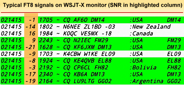
Do Digital Modes like FT8 work Below Noise?
Digital modes like FT8 work below Noise? – A myth It is a common myth that narrowband digital modes like FT8, JT65, etc establish communication with signals that are below the noise floor. This myth has by and large been perpetuated among the amateur radio community where many operators consider it to be a magical property of these digital modes. These narrowband digital mode signals may not be audible on a regular radio receiver or may not be visible on the band-scope spectrum or waterfall displays of our transceivers but there is nothing magical about it. They certainly do not work with signals being below the noise floor. Barring a few modulation modes like the Spread Spectrum, including both direct Sequence Spread Spectrum (DSSS) and the Frequency Hopping Spread Spectrum (FHSS), typically most other commonly used digital modes need signals to be above the noise floor with a positive magnitude of Signal-to-Noise Ratio (SNR). Spread Spectrum due to its nature, has a very low signal density that typically lies below the noise floor. Hence, it is difficult to detect and... Click Here to Read Full Article […]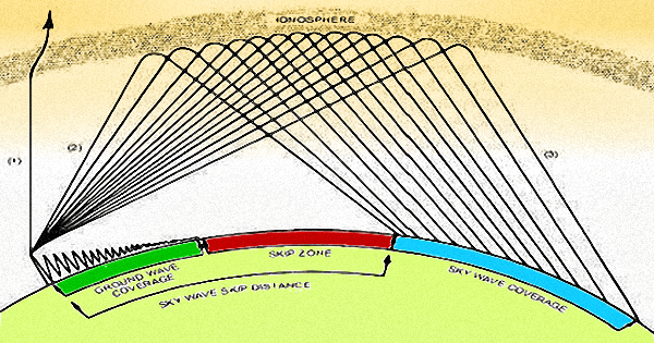
HF Surface Wave Propagation (Ground Wave)
HF Radio Surface Wave propagation (Ground Wave) Surface Wave propagation and coverage on the HF radio bands is well known to radio amateurs. Especially, on the Lower frequency HF bands called the Top Bands which includes the 160m band, though it’s technically an MF band. The surface wave propagation phenomena (also loosely termed as a Ground wave) plays an important role in supporting regional short-distance communication with a very high degree of reliability and robustness. Surface wave helps in filling the deaf region, if not fully at least partially that is created around the transmitter location. A region with a radius of typically several tens or hundreds of kilometers around the transmitter forms the skip-distance caused due to the ionosphere not always being dense enough to be able to return reflected (refracted) signals when they approach it at high angles of incidence. Those who might like to brush up the concept of a Skip-zone and Skip-distance could read through my post on the subject Skip Zone – HF. Although most of us have an intuitive understanding of the basic concept... Click Here to Read Full Article […]
Radio Rigs
What are Radio Rigs for Amateur Radio? Radio rig is a generic term used by an amateur operator for the radio station equipment. It includes not only the primary transmitter and receiver (or transceiver) but also various other peripherals and station accessories. Although the transceiver performs the core function, several other pieces of hardware work in tandem to make radio communication more efficient. Often an outboard transverter, converter, low noise RF pre-amplifier, linear PA, inline SWR meter, antenna tuning unit (ATU), antenna switcher, iambic keyer, morse key or paddle, panadaptor, scanner, CAT interface unit, antenna rotator control, etc are quite common. These radio rig accessories form a part of station operation. There is however another vital category of equipment that is needed for testing, calibration, and routine station performance evaluation. These include antenna analyzer, oscilloscope, frequency counter, and standard, spectrum analyzer, dummy load, absorption power meter, RF signal generators, two-tone oscillator, etc. Communication ReceiversThe basic architecture of a communication receiver is similar to that of a domestic broadcast receiver. They have RF preamplifier, mixer, oscillator, IF amplifier, demodulator, AGC and... Click Here to Read Full Article […]
(1 votes, Rating: 5.00) - Please vote the article with your valuable star rating. Thanks! Basu (VU2NSB)


Ham Rig Reviews Coming Soon
SSN SSNf(10.7) – Real-time Solar Data