Archive for 2020

100W on a Wire Antenna – How far would it reach?
100W on a Wire Antenna – Is it good enough for DX? 100W on a Wire antenna! … How far could it possibly reach? This is perhaps one of the most hotly debated rookie topics in the world of amateur radio. It has always been like this and it would always be the same. A radio amateur who has been newly initiated into this field takes a while to come to terms with reality. Intuitively, it becomes very difficult for a rookie operator to even imagine that 100W on a Wire might be more than adequate to communicate around the entire world. At times, a station with a plain-Jane dipole antenna and running as low as 5-20W may comfortably work the world. When I say this, I do not mean working via weak-signal digital modes like FT8, FT4, etc. The operating situation cited above refers to radiotelephony SSB QSO. However, for all this to be viable on a reasonably regular basis, there are a few fundamental prerequisites. First of all, the station operator would need to acquire a fair understanding... Click Here to Read Full Article […]
Understanding Antennas – The Good, the Bad, and the Ugly
Understanding Antennas – What makes them good or Bad? Are some antennas good while some others are bad? Many people seem to think so, but this notion is not entirely correct. Any such binary black or white classification is not the way to assess antennas. The fact of the matter is that all antennas that have been designed to radiate RF energy efficiently are usually good in their own rights. Yet I concede that the operator’s experience with a specific type of antenna may indeed be either good or bad. However, this does not necessarily mean that the fault lies with the antenna. More often than not it is the operator’s judgment in selecting the antenna or the way it is deployed that makes all the difference. Unless the antenna in question is technically a poor design that does not allow effective radiation to occur or the structural material used for fabricating the antenna leads to high loss resistance in comparison to its radiation resistance, there is no reason why the antenna will not be able to do the job... Click Here to Read Full Article […]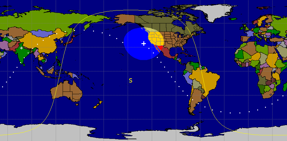
How to get started on ISS Cross band Repeater?
Getting started on ISS Cross band Repeater The new version of the ISS Cross Band Repeater had been activated on 2nd September 2020 at 01:02 UTC. Since it is still in the testing and deployment phase at the time of writing (October 2020) of this article, its service might currently be available on an intermittent basis. Nevertheless, this should be great news for millions of radio amateurs around the world as it is indicative of was is in store for us in the coming days. The ARISS program (Amateur Radio on International Space Station) has been active for many years. Under ARISS, a variety of amateur radio communication activities have been conducted at specified times as per declared schedules. Amateur radio operators around the world have made numerous FM radio voice contacts with astronauts onboard the ISS as well as received SSTV picture transmissions from the ISS. However, the above activities in the past required adherence to ISS activity schedules. Radio amateurs could make radio contacts with the astronauts but only when they were free to operate amateur band radios…... Click Here to Read Full Article […]
Impact of VHF-UHF Radio Repeater Site Location on Coverage
VHF-UHF Radio Repeater Site Location vs Coverage The significance of VHF-UHF radio repeaters’ site location for achieving the desired reliable coverage range cannot be taken lightly. Adequate due diligence is required in terms of assessment of the topology of the territory to be covered. A radio repeater site that is located on a high elevation geographic feature would usually provide a technically viable option. Of course, the physical logistic viability of the site is also equally important. Some geographic features might be technically excellent but might be difficult to access and hence might not be logistically viable. Therefore, site selection is often a tricky process that could require a lot of thought. Needless to say, depending on the topology of the land, at certain places, the best choice of a radio repeater site might be obvious and quite intuitive. For instance, a city with a hill on the outskirts that is visible from all across the town would be an ideal choice. Similarly, a suburban or rural area on a plain terrain could be served sufficiently well by a radio... Click Here to Read Full Article […]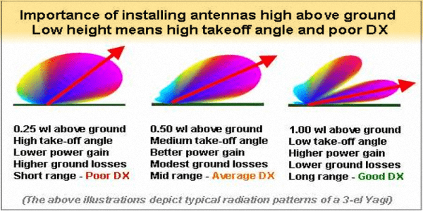
Why might Antenna Height matter more than Gain
Does antenna height matter more than gain? Though it may seem to be paradoxical at first sight, the fact is that very often the antenna height above ground might matter more than its published gain when it comes to HF band antennas used for DX operation. Long-range DX contacts on HF bands typically require long skips on optimally selected frequency bands for best results. To achieve this objective, the radiation takeoff angle (TOA) has to be quite low. Especially, under low SSN conditions (as is prevalent at the time of writing this post), when the ionospheric plasma densities are low and the slab thickness is also less, the higher TOA signals might penetrate the ionosphere to be lost in outer space. Low TOA signals from the antenna provide us the best prospects. Does this mean that we need to search for some special kind of antenna with low TOA capability to deploy at our QTH? NO! We don’t… Every antenna can be installed in a manner so as to provide low TOA, however, the user must be aware of how... Click Here to Read Full Article […]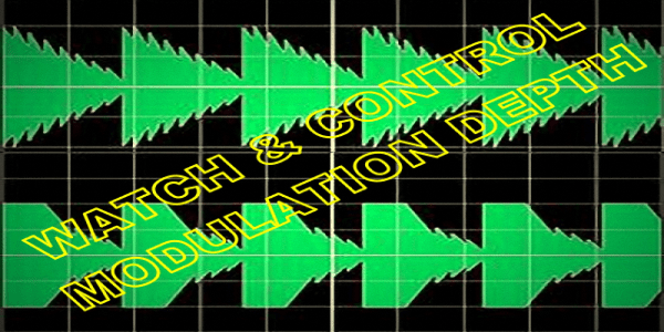
Watch Radio Modulation Depth for best Signal Clarity
Set Radio modulation Depth for optimum Clarity For the sake of optimum clarity and intelligibility of radio transmission, the radio modulation depth must be controlled by ensuring that the microphone input level is maintained well within the automatic Level control (ALC) correction range of the modulator. Failure to do so would result in the introduction of audio distortion. Overdriving the modulator will invariably result in the creation of unwanted AF harmonics and spurious products. Consequently, the intelligibility of the demodulated audio on the receiver at the DX end will also suffer proportionately. Several ill-effects of overmodulation will begin to surface. In extreme cases, the overmodulating radio station will begin to splatter across the band. However, with the modern radio transmitters, sideband splatter is usually not the problem. Nonetheless, this could have been a huge problem in earlier transceivers because it would have produced spurious RF components across a significant portion of the band. At times the splatter could have extended across the entire band. This kind of slatter from just one operator might have rendered the band more-or-less useless for... Click Here to Read Full Article […]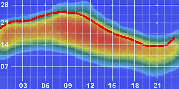
Global HF Radio Propagation Openings – The Summer of 20
HF Radio Propagation Outlook – The Summer of 2020 In the Summer of 2020, the HF Radio Propagation openings are not so frequent as one would expect under normal circumstances. The reason, as we all know is on account of the phase of the 11-Year Sunspot Cycle that we are going through at this time. The 24th Solar Cycle has ended while the 25th cycle has yet to pick up steam. We are placed at the cusp, which appears like a deep broad valley when observed on a graph. As a consequence, the prevailing SSN is either extremely low or zero (0) most of the days. The 10.7cm Solar Flux Index (SFI) is also near the rock bottom. The solar magnetic activity, as well as the energy and particle ejections, are rather placid and limited. For our friends living on the Southern side of the Equator, the phrase, Summer of 2020, may not sound right because it is the winter for them. I totally acknowledge this reality but would request them to bear with me on this matter with regards... Click Here to Read Full Article […]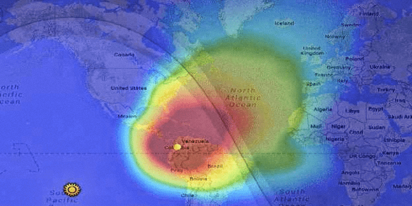
A Typical 40m HF Band Opening – A Graphical Rendition
40m HF band opening – Animated view Here is an animated graphical rendition of a typical 40m HF band opening transition scenario that I have modeled to provide a pictorial insight into the process. Any animated graphical rendering of HF band propagation opening as it gradually unfurls with the passage of time over the global canvas is a treat to watch. We all know that as a band opening begins to occur, the radio propagation prospects into distant land begin to unfold. This is a gradual process and is primarily dependent on the rotation of the earth on its axis leading to a change in illumination of the globe by solar radiation. As we daily progress through the diurnal (day/night) variation, we expect these changes to play out. On account of the above phenomena, the plasma density of the ionospheric layers above the earth also continuously alters their characteristics in terms of their charge densities, thickness, and height. During the night, the D-layer dissipates while the E-layer practically disappears due to excessive thinning of its plasma density. The F1 and... Click Here to Read Full Article […]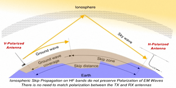
How vital is Antenna Polarization in Radio Communication?
Antenna Polarization in Radio Communication What is the significance of antenna polarization in radio communication? Or, should we ask, how does the polarization of radio waves affect radio communication capabilities? We surely need to understand the fundamental concepts and find out the probable practical effects. By-and-large, most of the antennas that we use on a regular basis are linearly polarized and hence produce linear polarized radiations. Although there are several types of antennas that produce circular (LHCP or RHCP) polarization, they are relatively rare in terrestrial communication application scenarios. Satellite-based radio communication often uses circular polarized antennas both at the satellite and the earth station end of the links. However, that’s a story for another day… Or else, check out the article Amateur Satellite Communications. Moreover, the circular polarization throws up its own set of challenges related to polarization rotation directions. As amateur radio operators, generally engaged in terrestrial radio communication, we normally use linear polarized antennas. This is applicable to both HF as well as VHF/UHF communication. Typically, our antennas are oriented in ways to favor either Vertical or... Click Here to Read Full Article […]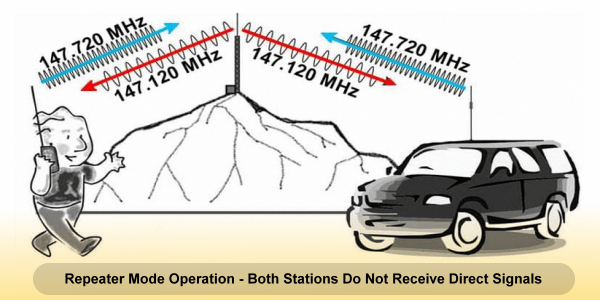
Why doesn’t 59 Signal Report on Repeater make sense?
Does 59 Signal Report on a Repeater make any sense? Does a 59 Signal Report exchange during a QSO on a Repeater make sense? Unfortunately, it doesn’t… We so often come across stations who report 59, or 59+20dB, etc to the other station during a QSO that is conducted through a local terrestrial repeater or during a QSO made via FM repeater type LEO amateur satellites. To top it all, I have come across instances where even a net-controller on an FM repeater net doles out this kind of signal reports to other stations and vice-a-versa. None of this makes any sense… Let’s see why? The RST reporting system comprises of three-digit. They are Readability (R), Signal-strength (S), and Tone (T). This is a typical CW signal reporting format most prevalent on HF radio bands. However, for radiotelephony, the third digit (T) is not applicable, and therefore only a two-digit (RS) report without the (T) is given. This is all good when it comes to regular point-to-point Simplex, Half-duplex, or Full-Duplex mode communication. How about repeater-based QSOs? The first digit... Click Here to Read Full Article […]
(4 votes, Rating: 5.00) - Please vote the article with your valuable star rating. Thanks! Basu (VU2NSB)


Ham Rig Reviews Coming Soon
SSN SSNf(10.7) – Real-time Solar Data


